Midmark® Smart G-Vacuum PC Board Test and Repair
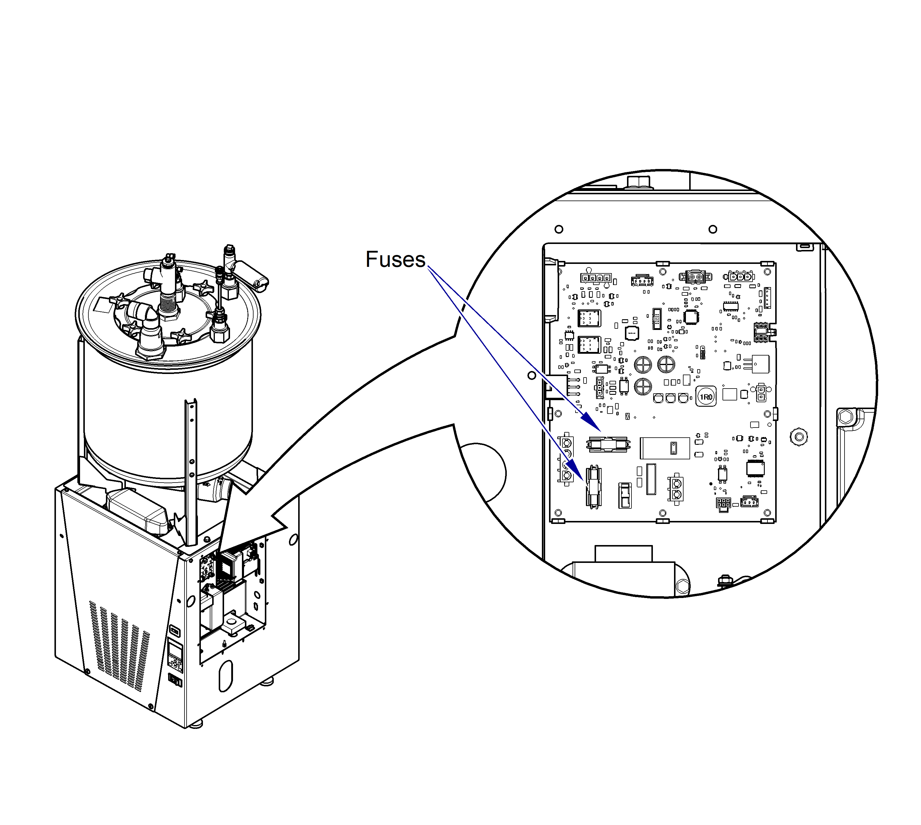
The PC Board is located in the electrical box and performs a number of various functions. These include: isolating circuits, main control for the unit, and provides a 24 Volt DC power supply to power the pressure sensor. The only serviceable parts on the PC Board are two fuses, however there are LED indicator lights for troubleshooting. The lights and connectors are all labeled on the board.
| LED Light | Label | Indicates |
|---|---|---|
| DS2 | OK | Blinking green when operating normally. |
| DS3 | 15V Power | Solid green when 15VDC circuit is functional. |
| DS4 | 3.3V Power | Solid color when 3.3VDC circuit is functional. |
| DS5 | Motor Enable MTR_EN | LED turns solid green when sending run command to motor. |
| DS9 | ERROR | Pulses red when first powering on. Flashes or remains solid red when there are errors in the system. |
When testing components with power on, use care to prevent electrical shock.
When working on Twin units, unplug parallel harness.
1.Turn power off at on/off switch and main power supply box. The separator tank should have drained when unit was turned off. Verify it is not full.
2.Remove electrical cover. Refer to: Electrical Cover
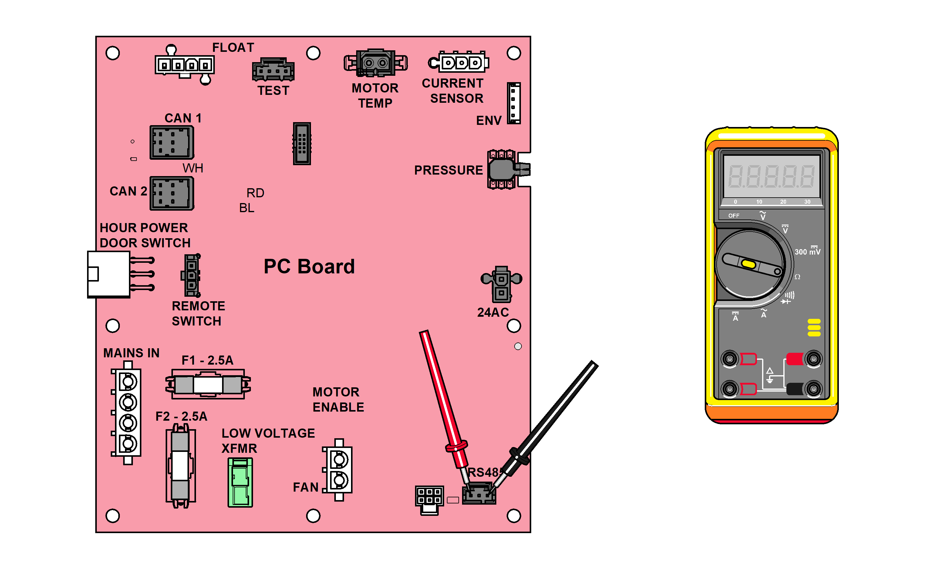
3.Before testing PC board, ensure F1 and F2 fuses are good. Refer to: Fuse And Transformer Test
4.Make sure the front cover is installed and the safety switch is engaged.
5.Turn main power supply and on/off switch on.
6.With the vacuum running, unplug wire harness from RS485 on PC board. Set meter to Ω. Test resistance at RS485 as shown.
Ensure the cable going to J12 is connected securely to avoid a false reading.
|
Meter Reading |
Required Action |
|---|---|
|
< 5 ohms |
PC Board Ok |
|
> 5 ohms |
Replace PC Board |
