630 Chair Tilt Actuator / Limit Switches Test and Repair
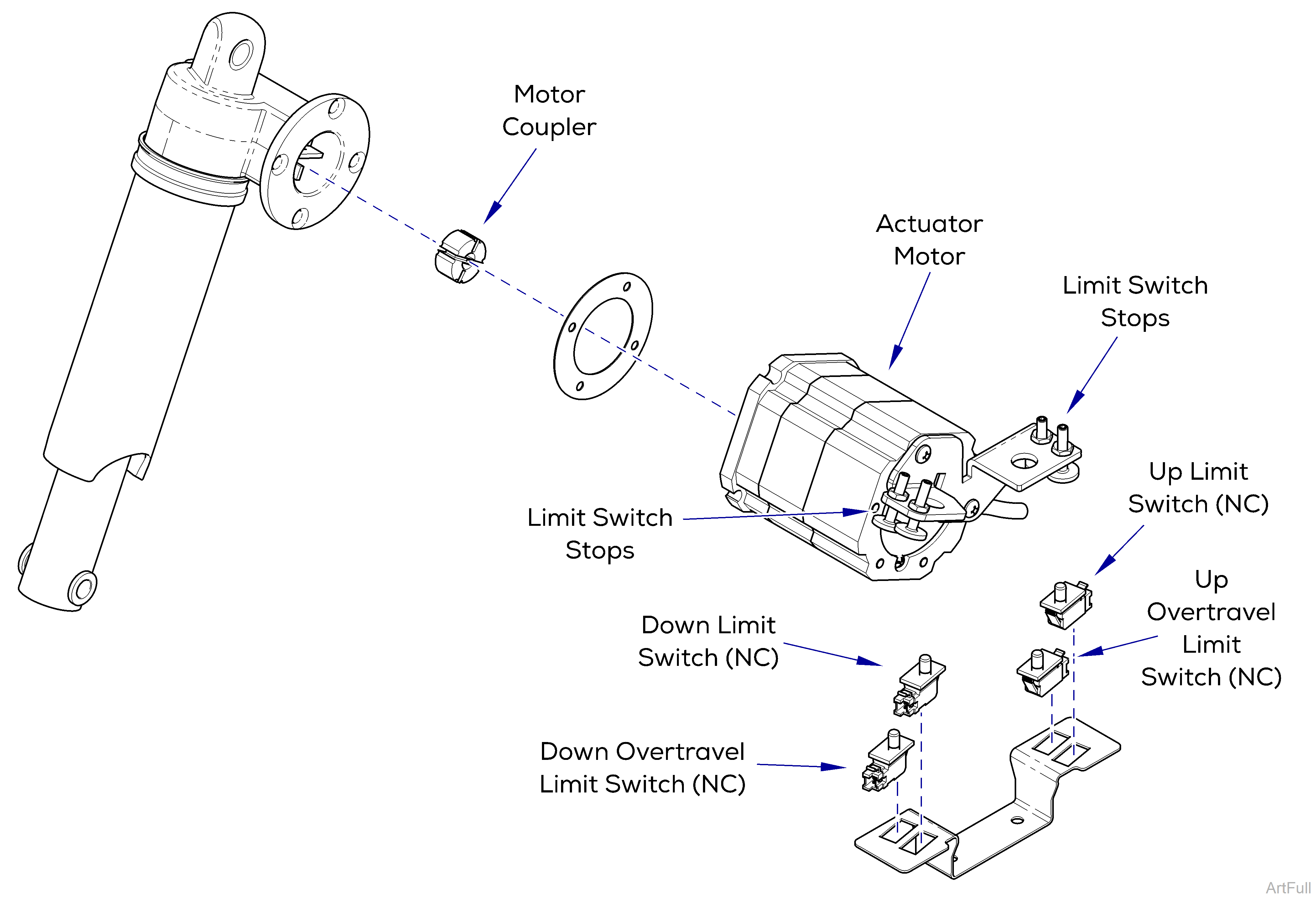
This illustration shows the tilt limit switches and the serviceable components of the tilt actuator. Use the table below to isolate the malfunction.
Anytime the limit switch wires or the actuator wires are disconnected, the PC Board must be calibrated.
Limit Switch Stops are preset at factory. Do not adjust or damage to chair may occur.
Anytime an Overtravel Limit Switch is detected open, both Up and Down functions are deactivated.
| Problem | Required Action |
|---|---|
| Motor runs, but makes grinding noise | Clean / lube actuator threads. Lube threads w/lithium grease. Replace actuator if necessary. |
| Motor runs, but chair does not move | Inspect / replace motor coupler |
| Motor does not run | Test Limit Switch(es). Refer to: Tilt Actuator Test |
The wire connections and wire routing must be put back in original locations before installing covers.
Failure to move all three connections may result in damage to chair.
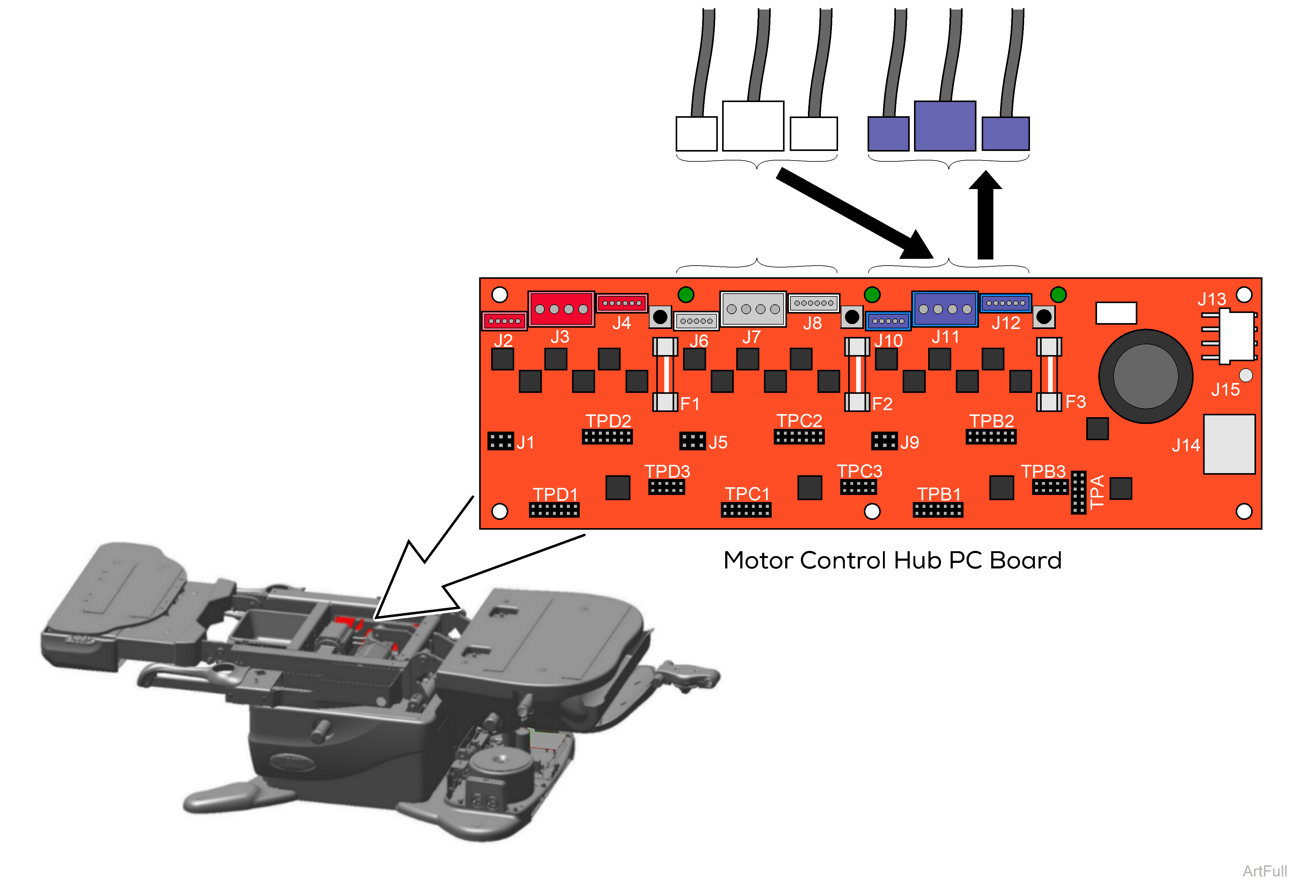
1.Disconnect power to the chair.
2.Disconnect Back actuator connections.
3.Move Tilt wire connection J6 to Back PC Board connection J10.
4.Move Tilt wire connection J7 to Back PC Board connection J11.
5.Move Tilt wire connection J8 to Back PC Board connection J12.
6.Connect power to chair.
7.Using the hand / foot control press and hold Back up button briefly and then press and hold Back down button briefly. Did Tilt move Up and Down in Step 2? If Yes, Actuator is OK. If No, Refer to: Tilt Actuator Motor Resistance Test.
8.Reconnect Tilt actuator connections.
9.Reconnect Back actuator connections.
10.Calibrate Chair. Refer to: Calibration Procedure
Anytime actuator wires are disconnected, the chair must be calibrated.
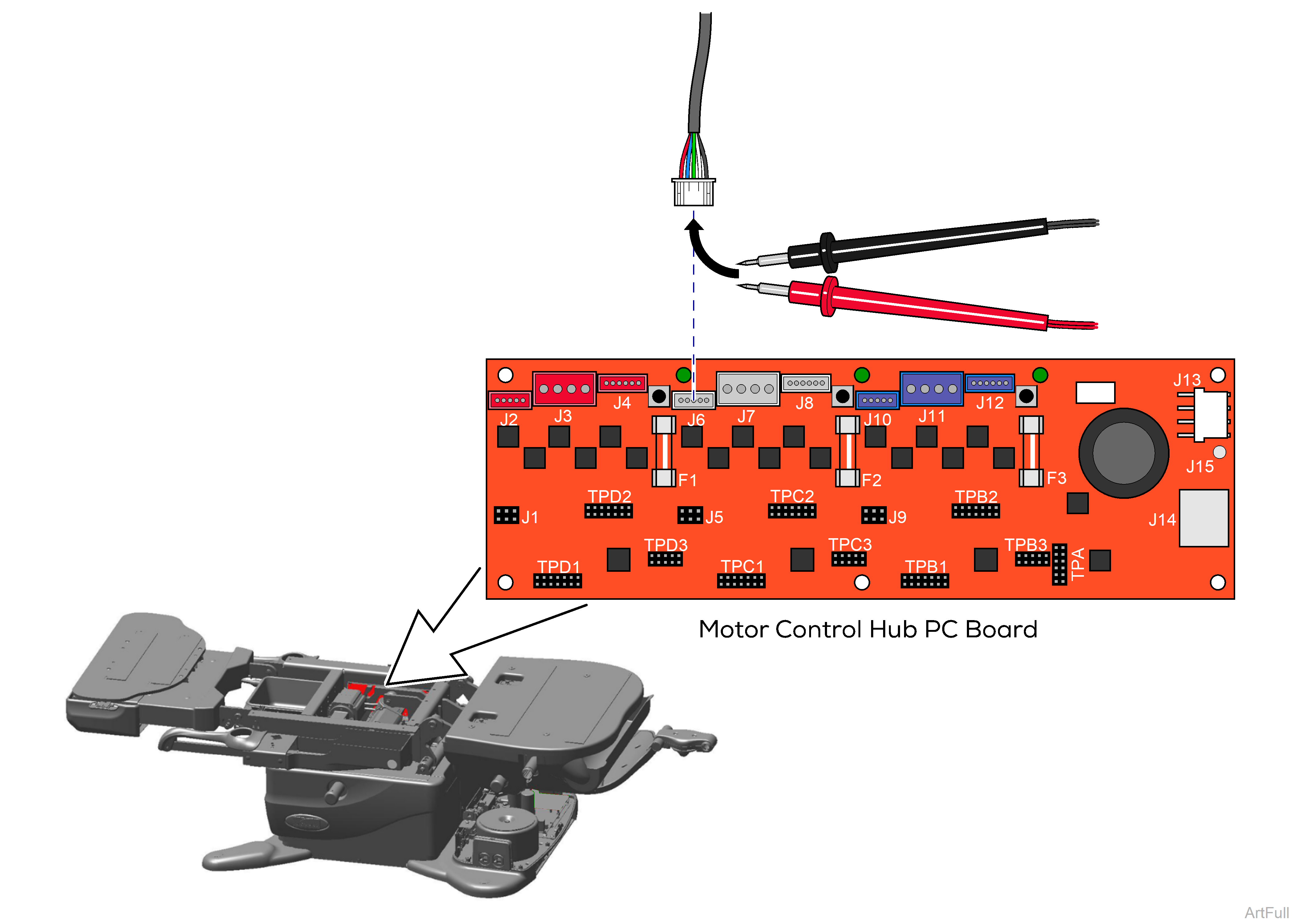
1.Disconnect power to the chair.
2.Disconnect tilt actuator from J6 on PC Board.
3.Set multimeter to Ohms to check resistance.
4.Place the Red meter probe on the Black wire, and the Black meter probe on the Blue wire.
5.Place the Red meter probe on the Black wire, and the Black meter probe on the Green wire.
6.Place the Red meter probe on the Black wire, and the Black meter probe on the White wire.
7.If any of the readings are less than two Mega Ohms after three seconds, the motor is defective.
