630 Chair Rotational Base Brake System Test and Repair
Always disconnect chair from power source before removing any covers. Failure to do so may result in personal injury.
1.Remove four screws from inner shrouds.
2. Raise base shrouds. Refer to: Raising Base Shrouds / Cladding w/ bungee cord.
3.Remove Brake Pedal. Pivot brake pedal toward column, then press down and push forward to release.
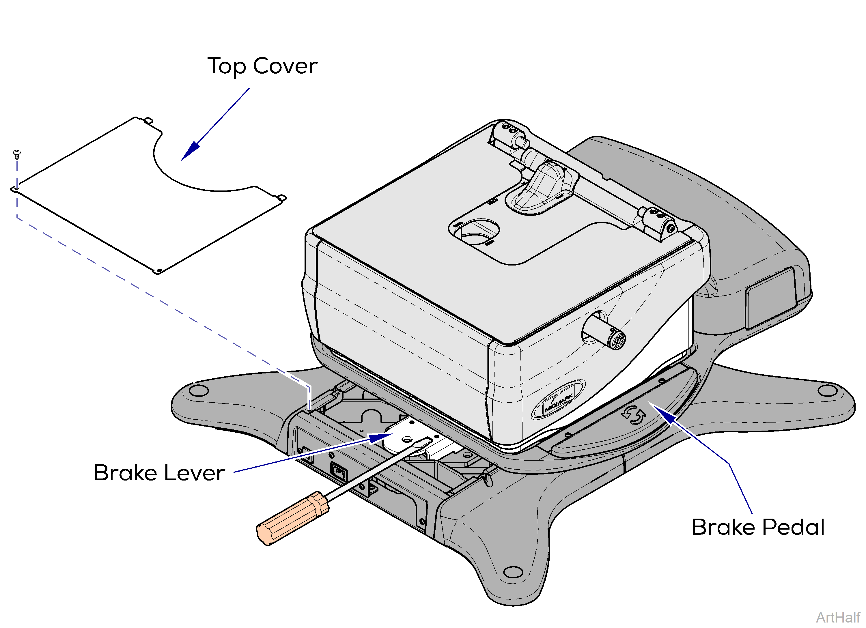
1.Rotate the base to access the rotational base top cover.
2.Remove two screws and rotational base top cover.
If the brake will not release, the base can still be rotated manually by applying additional force.
3.Hold a screwdriver on brake lever.
4.Press and release the brake pedal. Can you feel the Electro-magnet energize? If YES, Perform Magnet Position Adjustment. If NO, Check rotational base PC board. Perform Rotational Brake PCB Input Test.
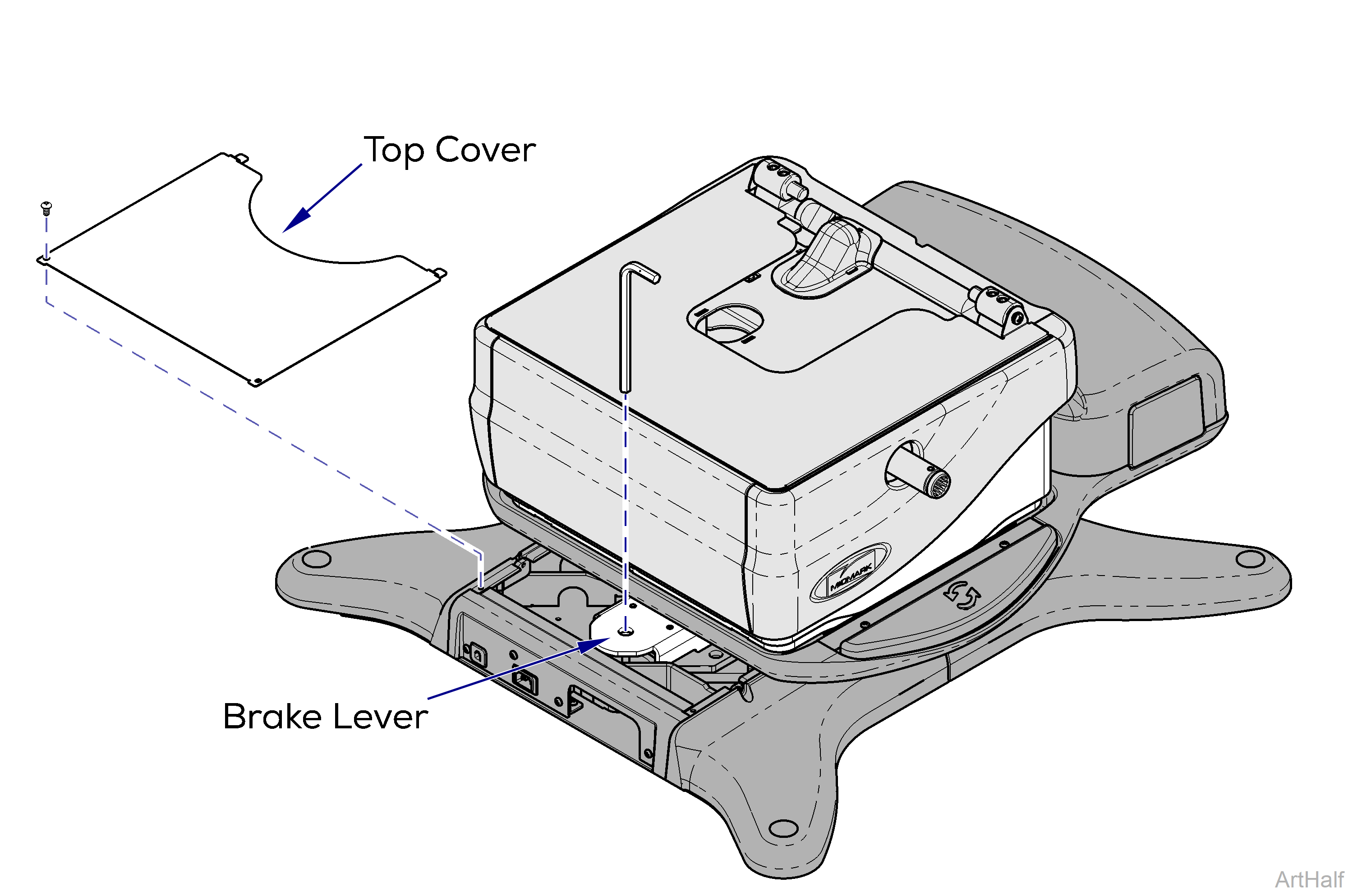
1.Rotate the base to access the rotational base top cover.
2.Remove two screws and rotational base top cover. If the brake will not release, the base can still be rotated manually by applying additional force.
3.Press the brake pedal while watching the brake lever. If the magnet “grabs” the brake lever tighten the magnet screw 1/4 turn. If the magnet does not “grab” the brake lever loosen the magnet screw 1/4 turn.
4.Check for proper operation. Repeat if necessary.
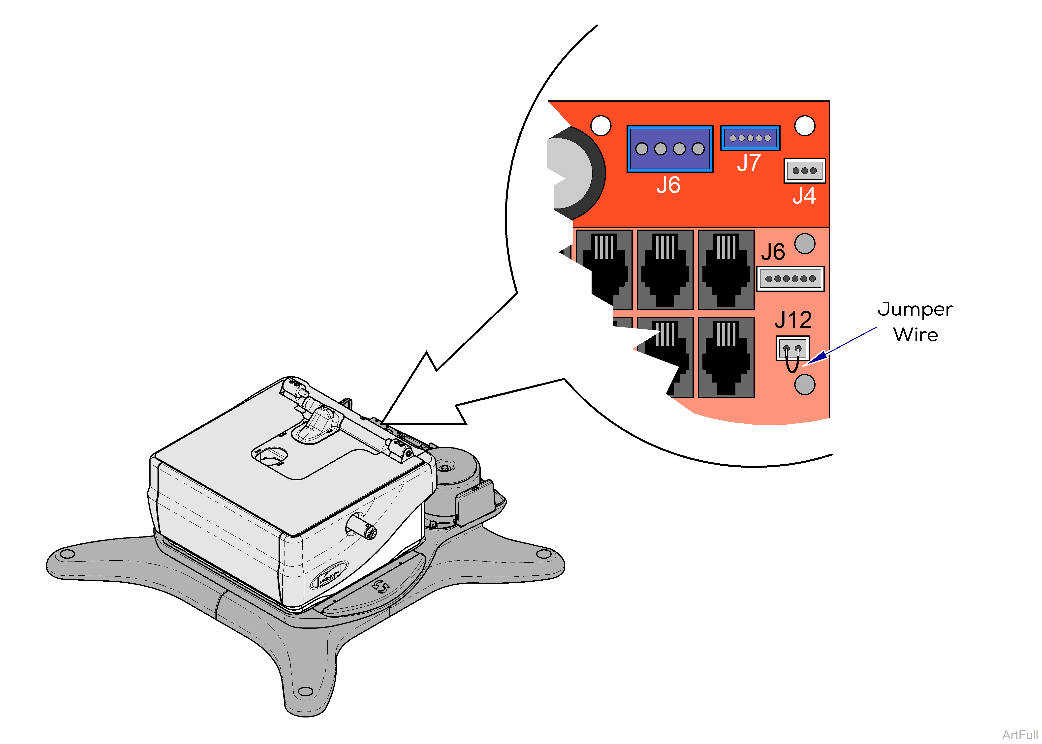
1.Remove PC Board cover.
2.Place jumper wire at J12 on Power Supply PC Board.
| Result | Required Action |
|---|---|
| Rotational Brake Activates | PC board is OK. Test brake pedal switch(s). |
| Rotational Brake Does Not Activate | Refer to:Rotational Brake PCB Output Test. |
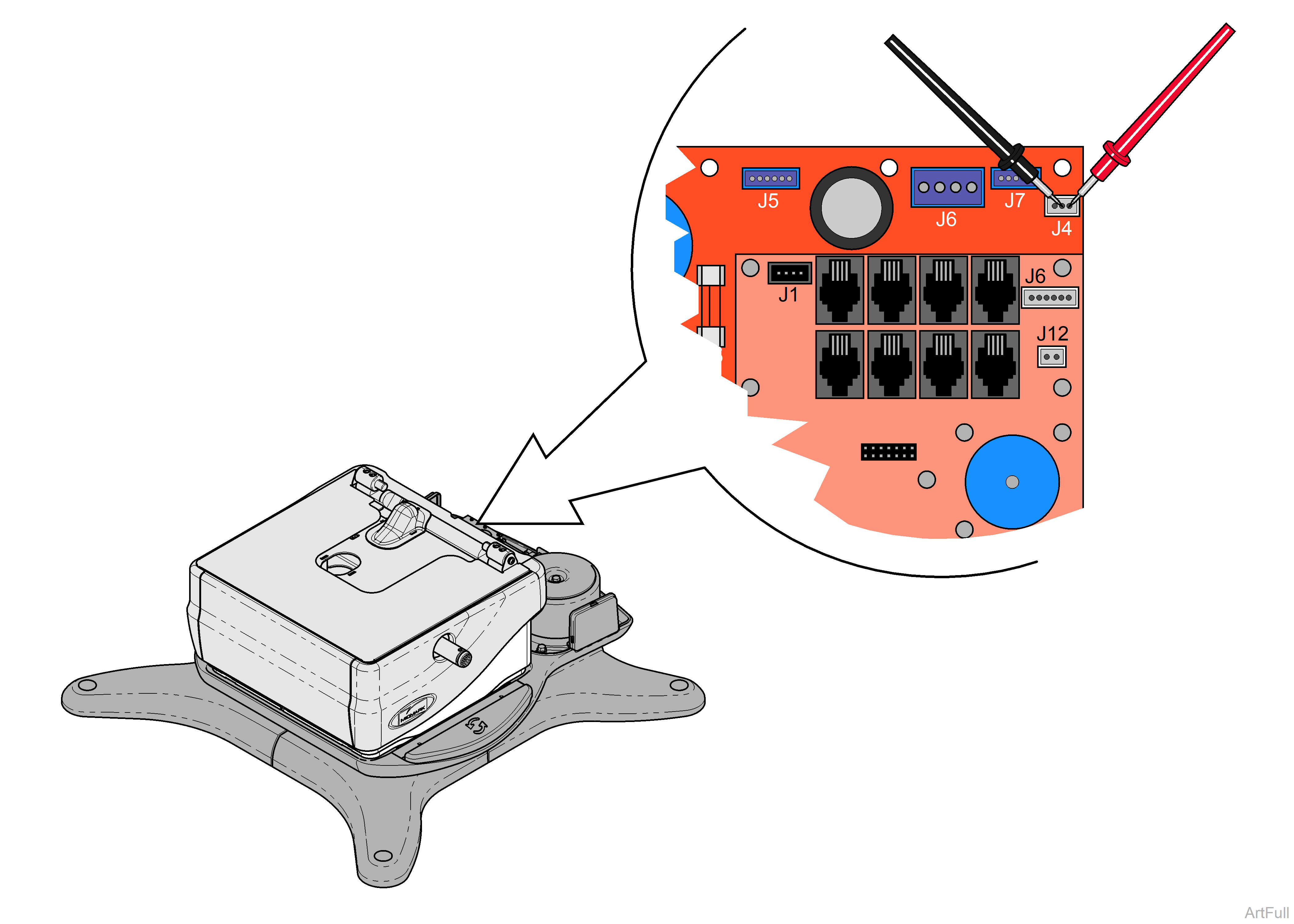
1.Remove PC Board cover.
2.Press and release brake pedal.
3.Place meter probes on middle and right pins at J4 on Power Supply PC Board. If no voltage is detected, press and release the brake pedal, then check again.
| Meter Reading | Required Action |
|---|---|
| 12-24 VDC | PC board is OK. Perform Electro-magnet Test. |
| 0 VDC | Refer to: Rotational Brake PCB Input Test. |
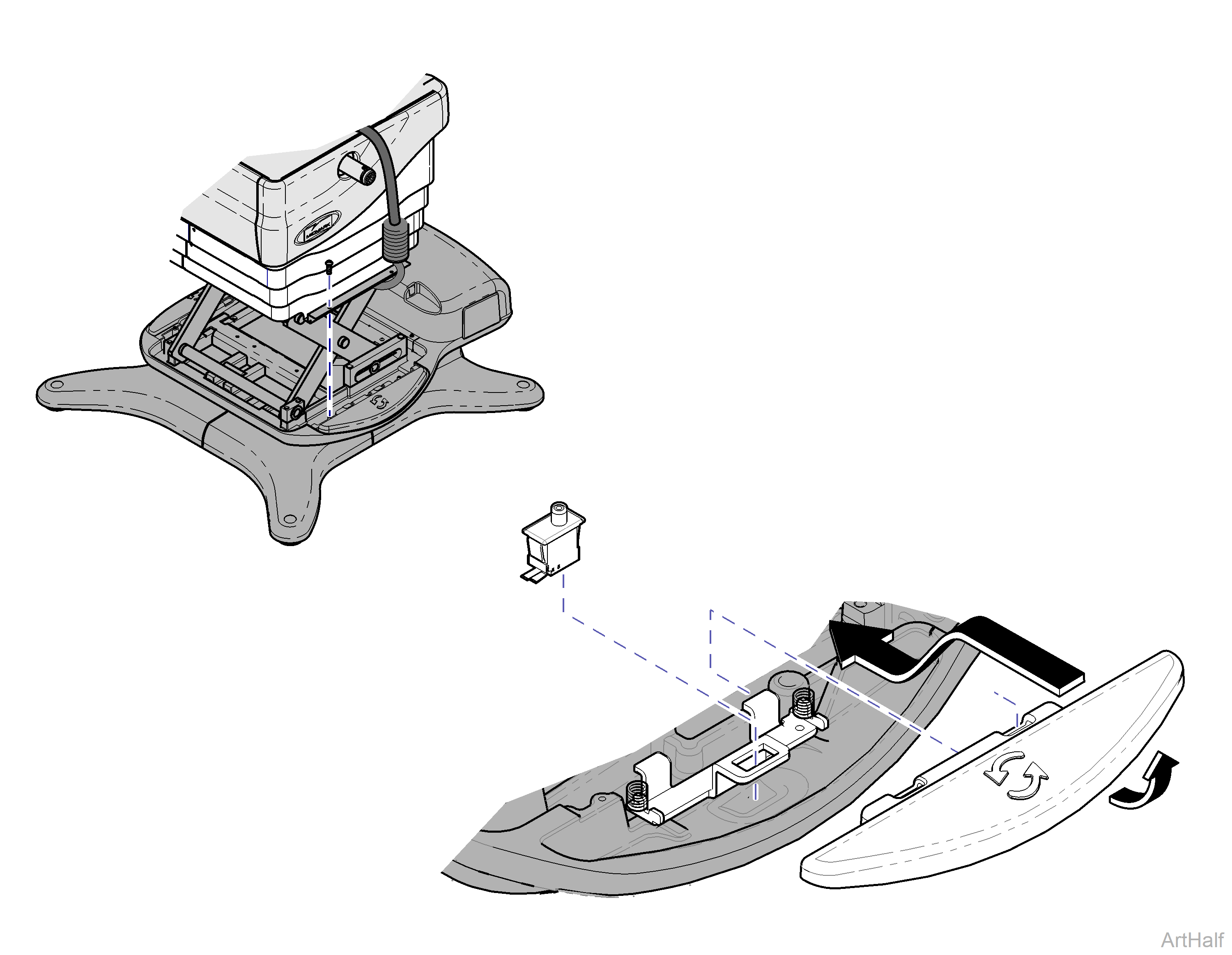
Rotational bearing components removed for clarity only.
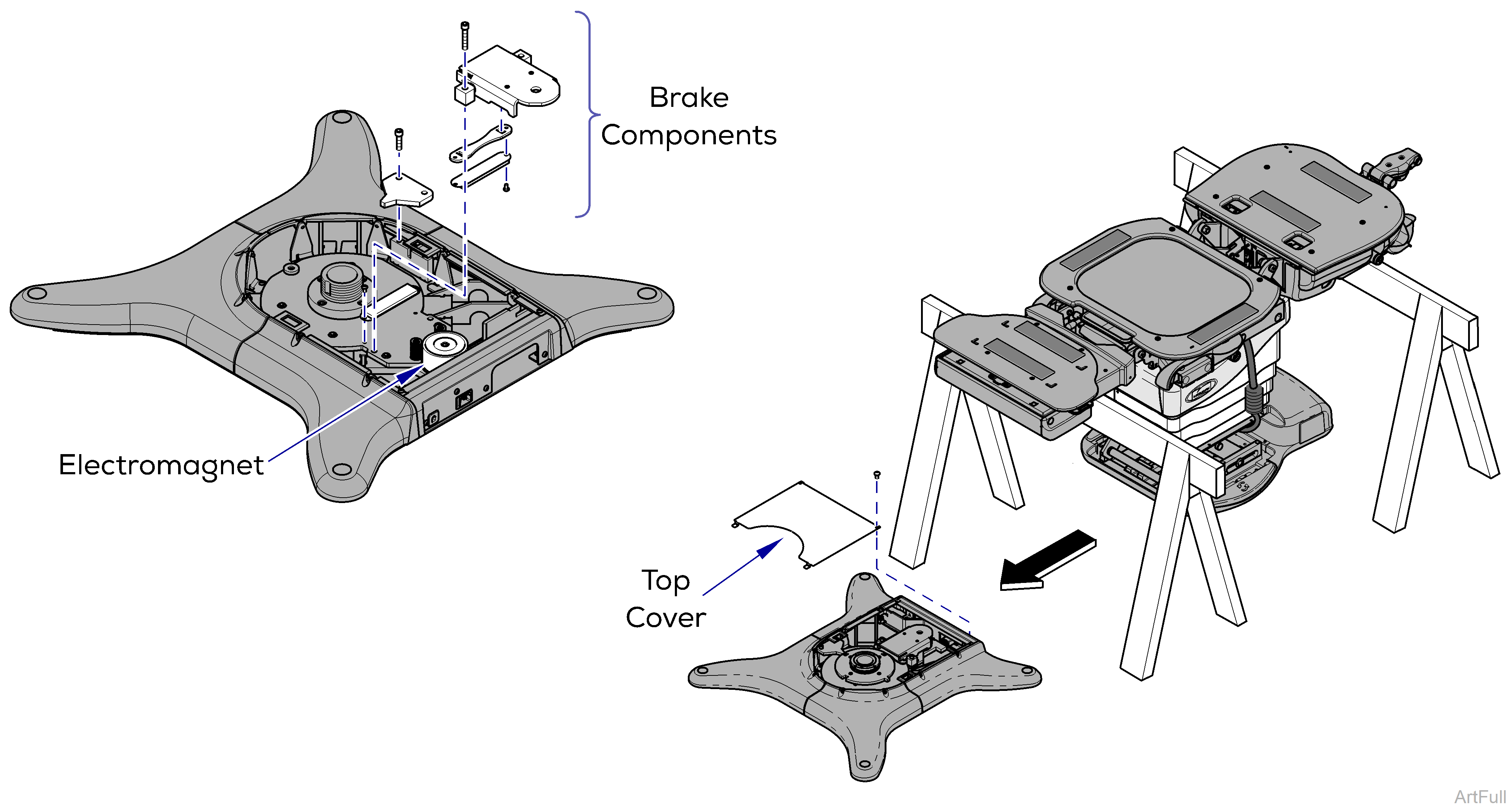
1.Separate upper and lower base castings. Refer to: Separating Upper and Lower Base Casting.
2.Remove lower base top cover. To reference a complete assembly breakdown, Refer to: Base Parts.
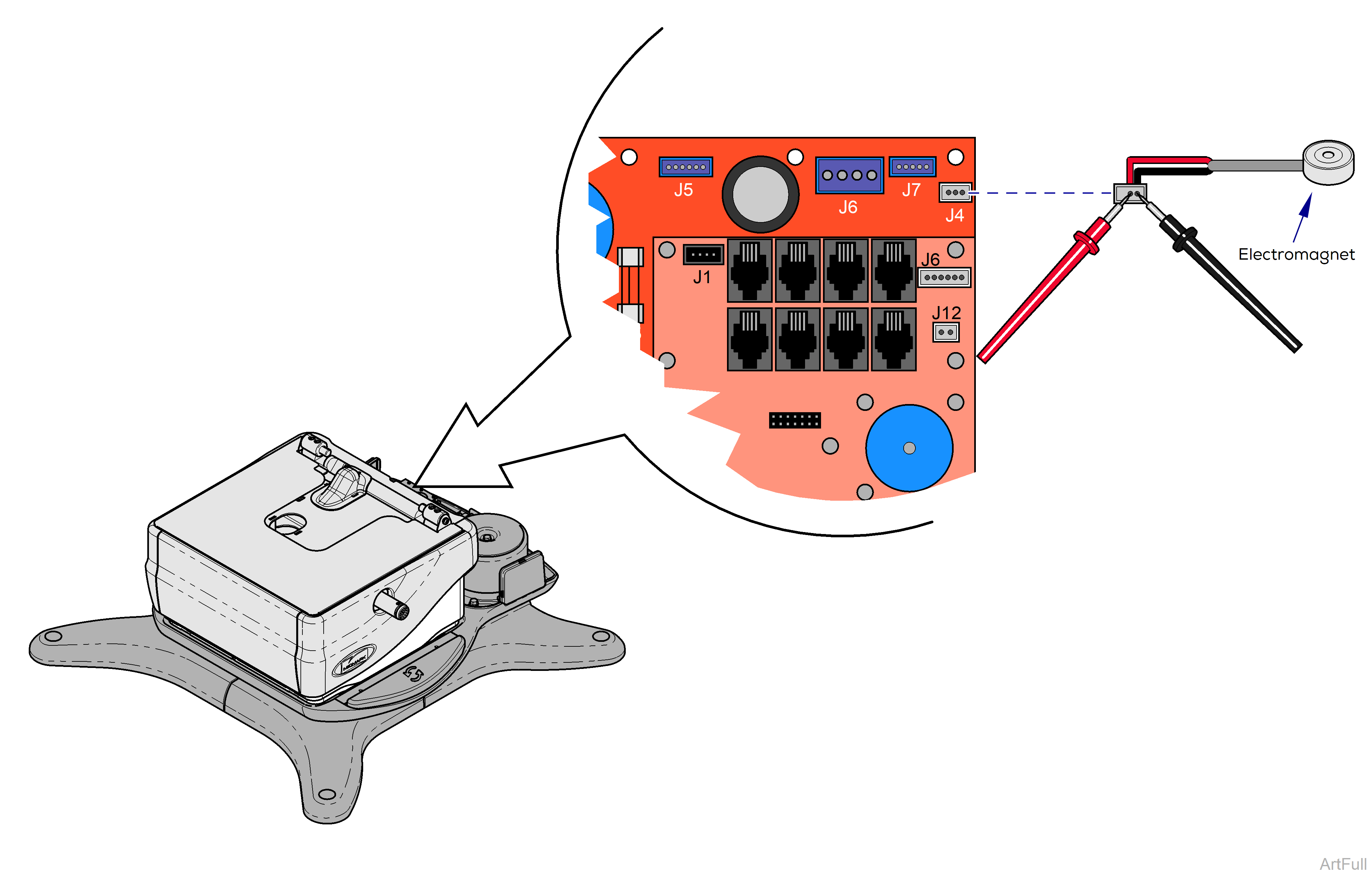
1.Remove PC Board cover.
2.Disconnect magnet wire harness. from J4 on Power Supply PC Board.
3.Place meter probes on Red and Black wire connections.
| Meter Reading | Required Action |
|---|---|
| approximately 10 ohms | Electro-magnet is OK. Check mechanical components. |
| OL or less than 5 ohms | Inspect magnet wire harness and wire connection in lower base. If OK, replace Electro-magnet. |
