641 Chair Back Actuator / Limit Switches Test and Repair
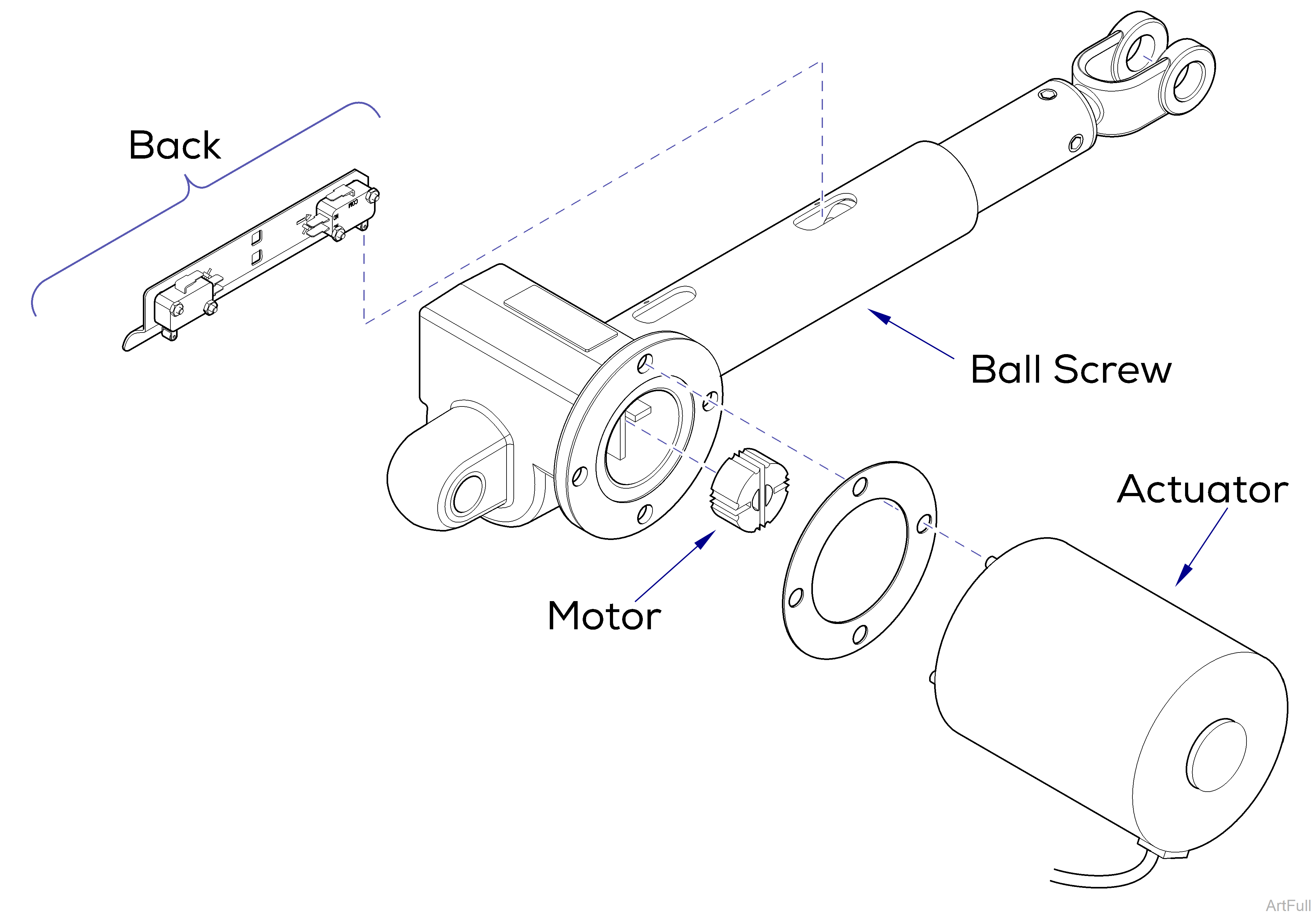
This illustration shows the back limit switches and the three serviceable components of the back actuator. Use the table below to isolate the malfunction.
| Problem | Required Action |
|---|---|
|
Motor runs, but makes grinding noise. |
Clean / lube actuator threads. Replace actuator if necessary. |
|
Motor runs, but table does not move. |
Inspect / replace motor coupler. |
|
Motor does not run. |
Check limit switch wire connections. If OK Perform Actuator Motor Test. |
Lube threads w/lithium grease.
Do not adjust the individual switches! The limit switches and bracket must be replaced as a complete assembly.
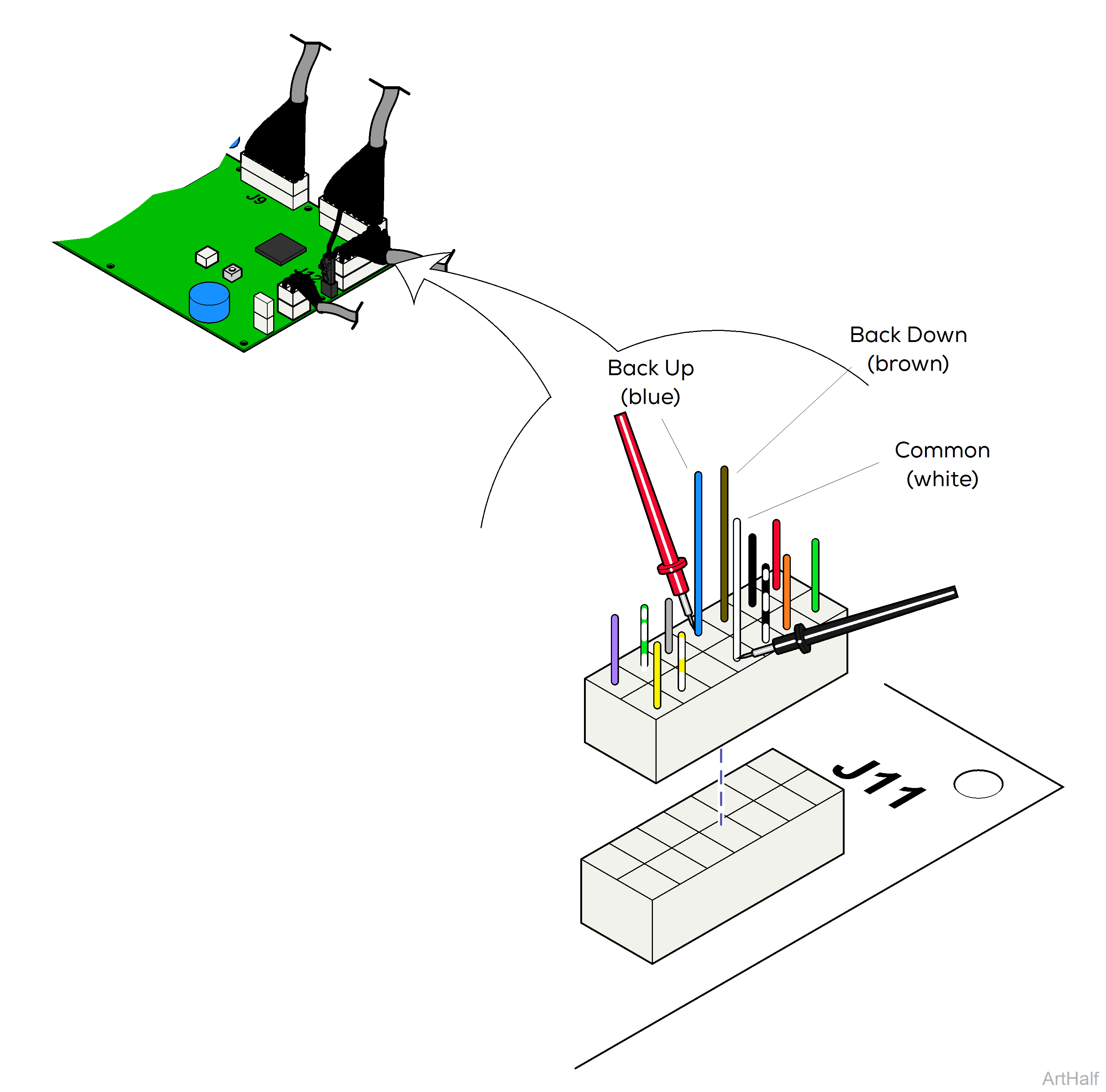
1.Disconnect harness from J11 on main PC board
2.Place one meter probe on the common - white.
3.Place other meter probe on the wire corresponding to the desired switch - see illustration.
Check switch tripped and untripped.
Back Down switch untripped OR Back Up Switch tripped
| Meter Reading | Required Action |
|---|---|
|
OL |
Perform Limit Switch Harness Test |
|
less than 10 Ω |
Limit switch / harness - OK, Perform Actuator Motor Test |
Back Down switch tripped OR Back Up Switch untripped
| Meter Reading | Required Action |
|---|---|
|
less than 10 Ω |
Perform Limit Switch Harness Test |
|
OL |
Limit switch / harness - OK, Perform Actuator Motor Test |
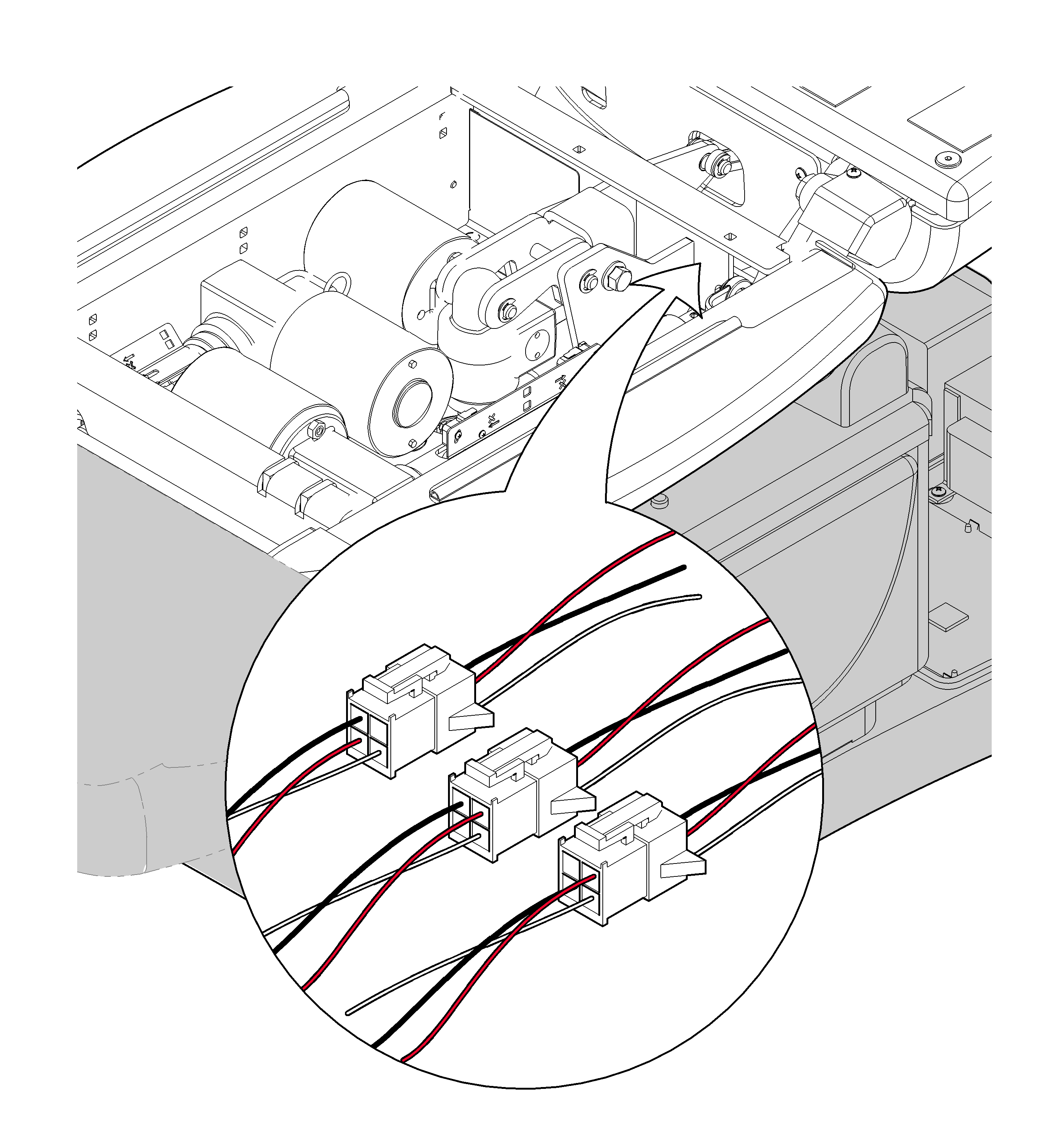
1.Unplug the appropriate limit switch harness.
2.Measure continuity.
| Meter reading should be | |
|---|---|
|
Actuator Full Up |
White to Black - Open |
|
Actuator Full Down |
White to Black - Closed |
|
Actuator Midway Point |
White to Black - Closed |
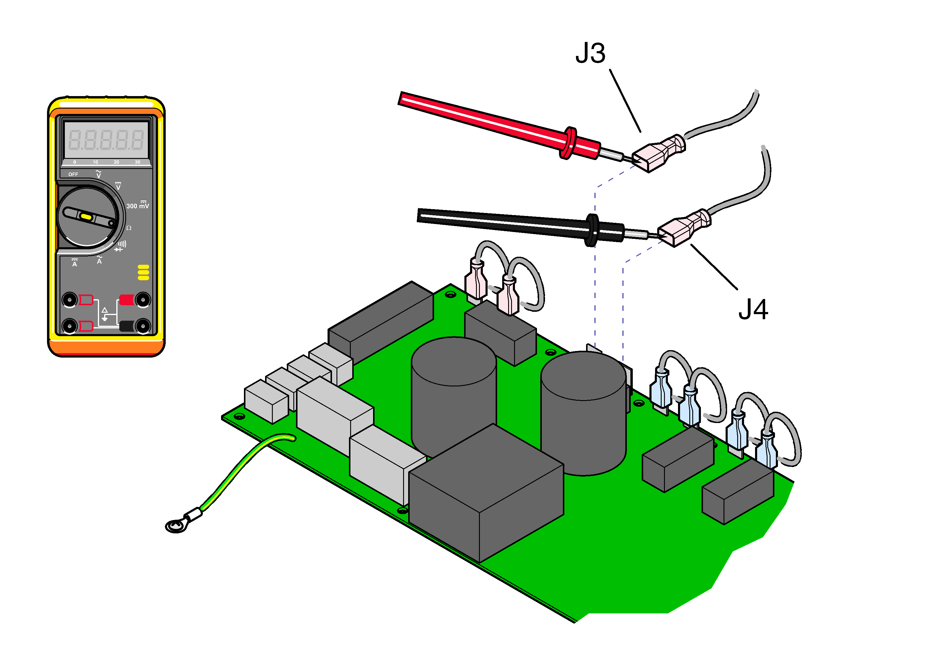
1.Tag / disconnect back actuator wires J3 and J4.
2.Place meter probes on actuator wires. Check meter reading.
| Meter Reading | Status | Required Action |
|---|---|---|
|
1 to 10 Ω |
|
Actuator motor OK. Perform Motor Ground Test |
|
OL or less than 1 Ω |
|
Replace motor. |


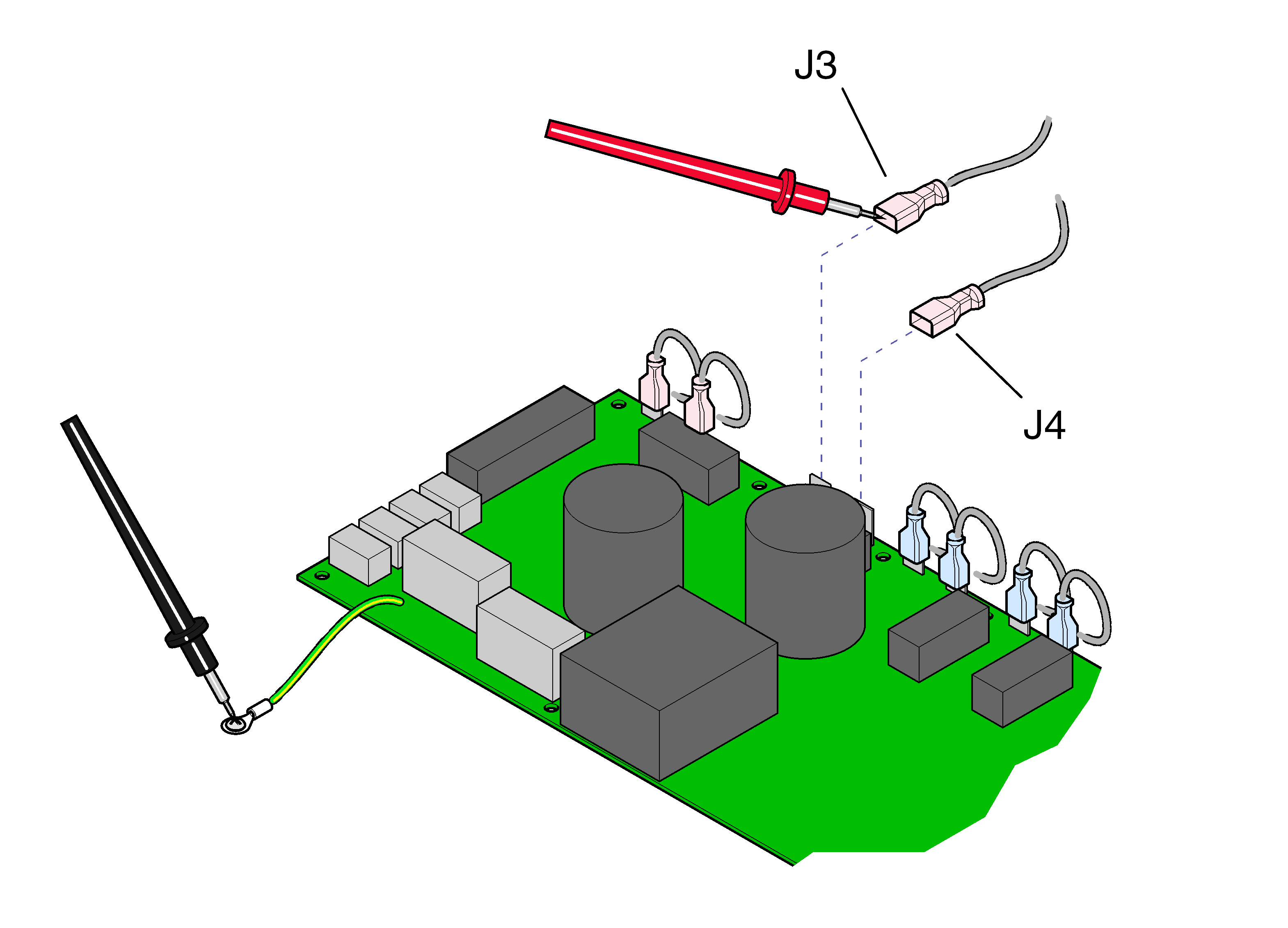
1.Place one meter probe on actuator wire J3. Place other meter probe on PC board ground wire. Check meter reading. Repeat for J4.
| Meter Reading | Status | Required Action |
|---|---|---|
|
OL or more than 1 M Ω |
|
Motor harness OK. Perform PC Board Test |
|
less than 1 Ω |
|
Replace motor. |
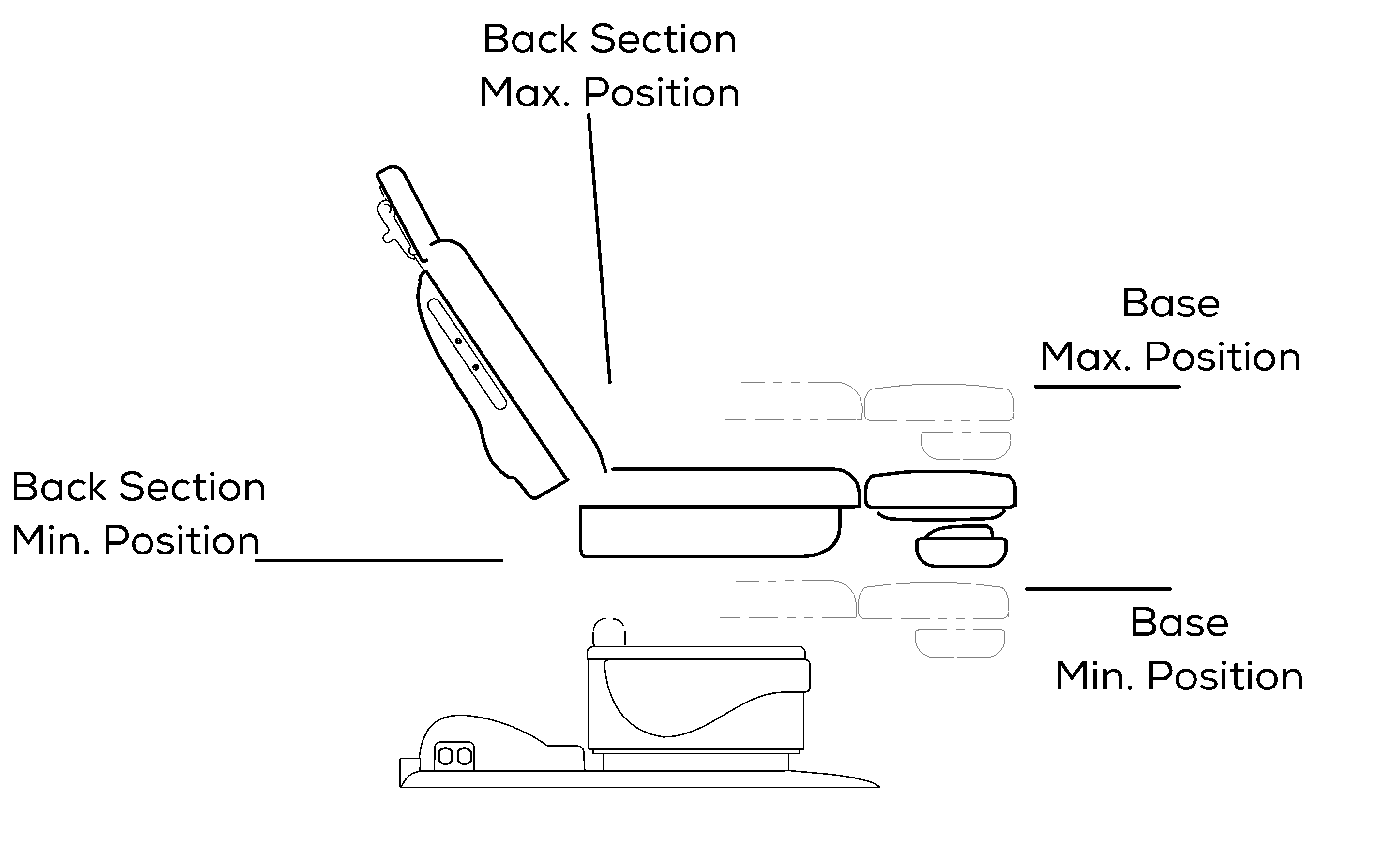
1.This test cannot be performed with the back section in the max. or min. position. If necessary, reposition the back section. Refer to: Base Actuator - PC Board Test.
2.Move the Base function so that it is approximately halfway between the maximum and minimum positions.
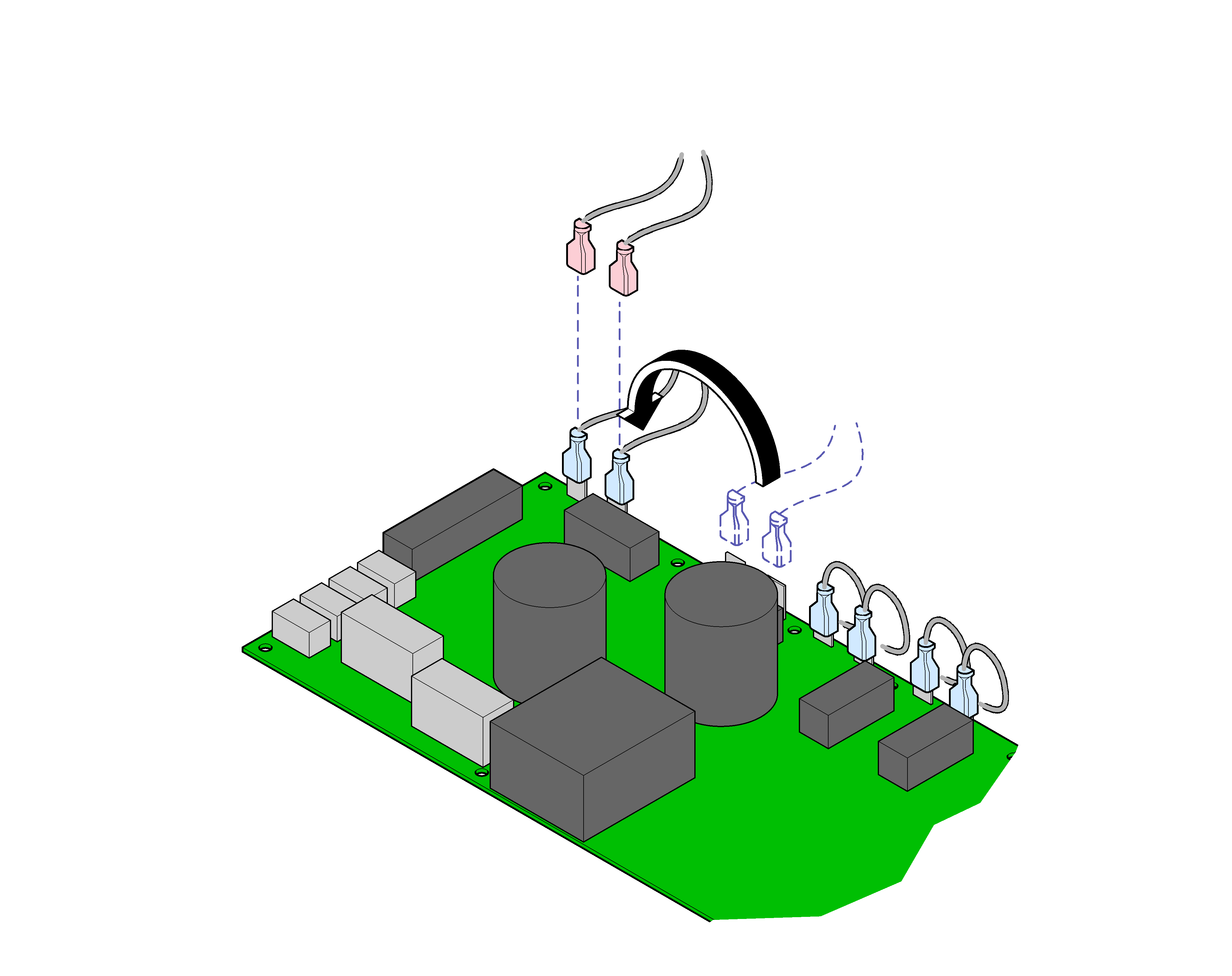
3.Tag, then disconnect back actuator wires from J3 and J4.
4.Move wire from J1 to J3. Move wire from J2 to J4.
The base limit switches will not stop movement during this test. Do not run past max. / min. positions.
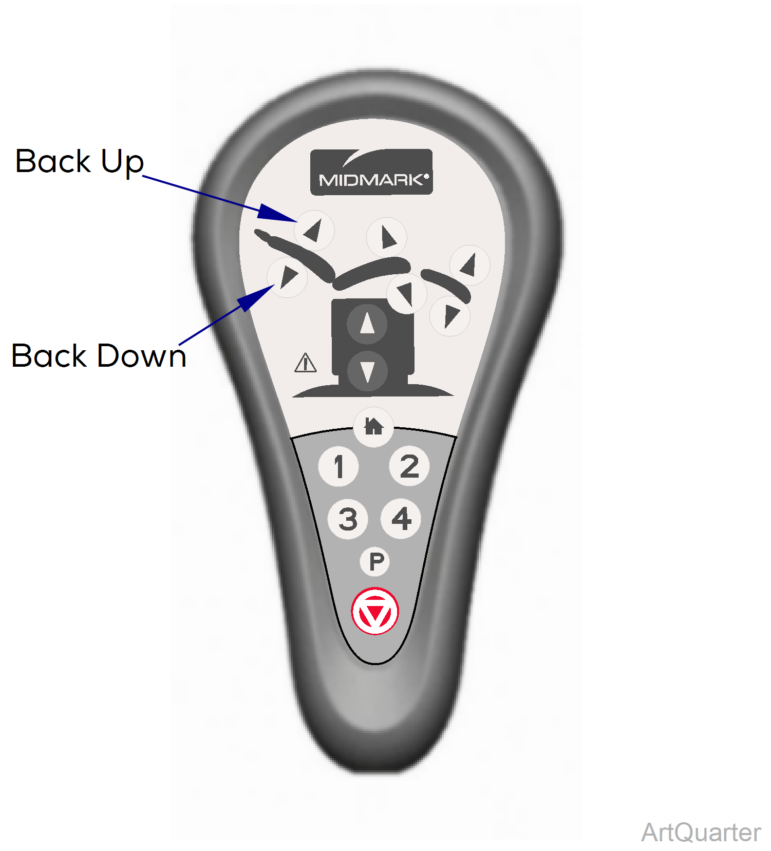
5.Press and hold Back Up button for 5 seconds. Does the base move up, then stop and beep? If Yes, go to Step 6. If No, replace PC Board*.
6.Press and hold Back Down button for 5 seconds. Does the base move down, then stop and beep? If Yes, PC Board is OK. If No, replace PC Board*.
