641 Chair Rotational Base Brake System Troubleshooting
|
Model |
641 -004 and -005 |
| Serial Number | All |
This illustration shows only the components that affect the Rotational Base Brake System. A detailed description of current flow during this function also appears below.
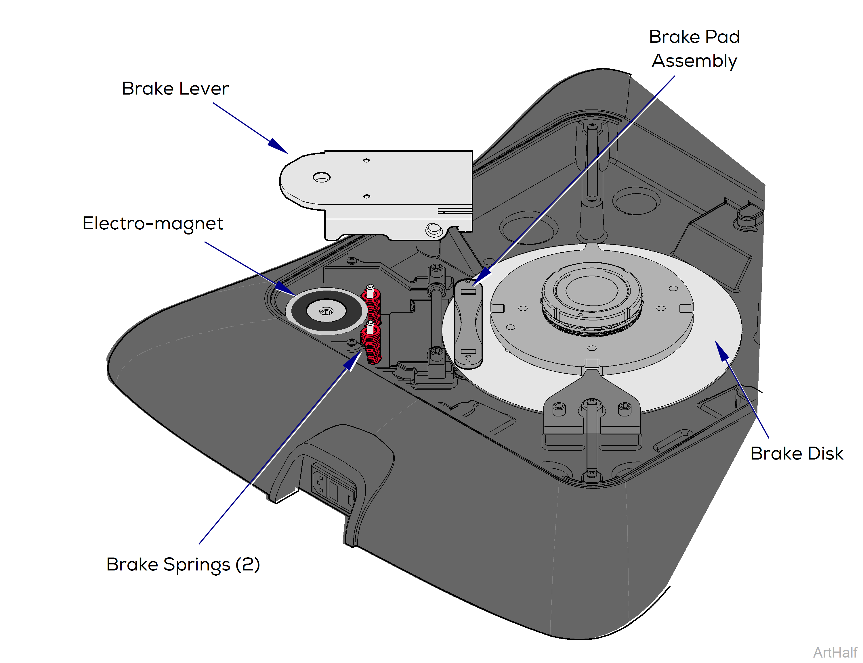
To lock and unlock base rotation press and release either brake pedal. Base automatically locks in place after 2 minutes.
Base Rotation Unlocked
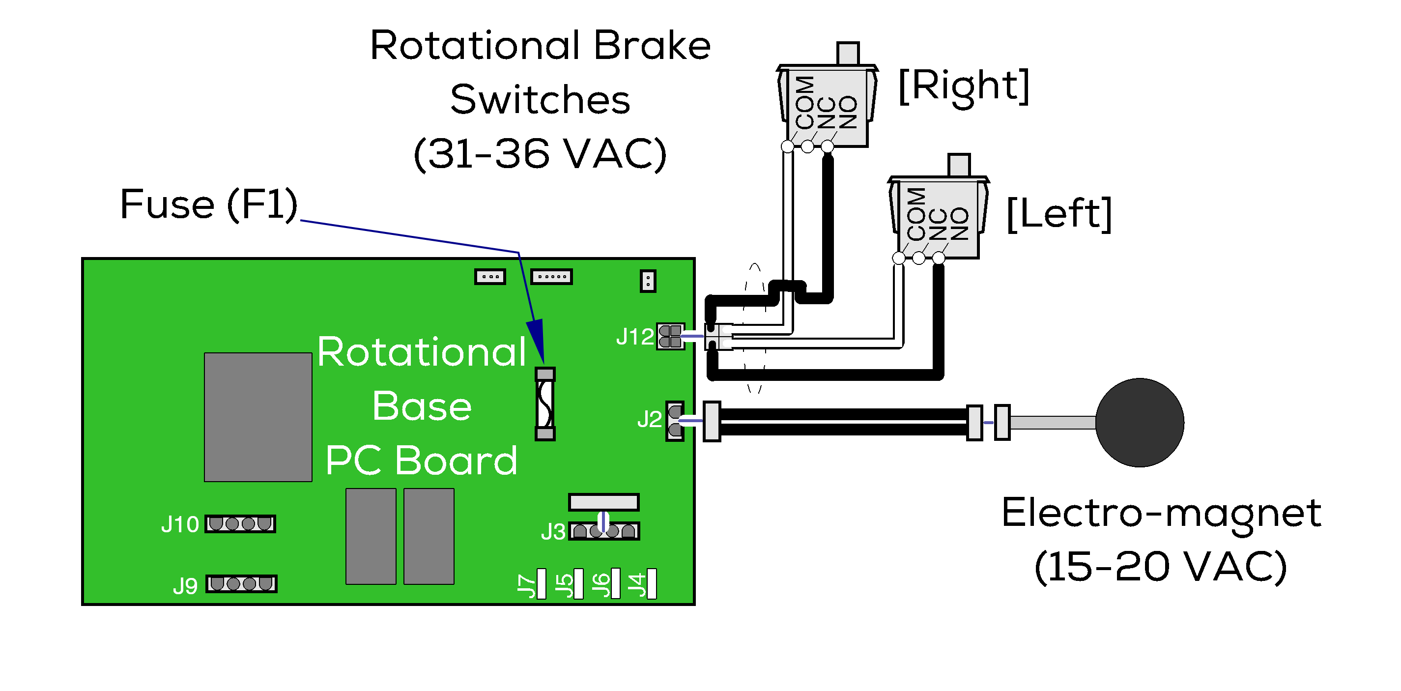
The rotational base PC board supplies 31 - 36 VAC to the two normally closed brake switches. When either brake pedal is pressed and released, the corresponding brake switch opens. When the open switch is detected, the PC board supplies approximately 15 - 20 VAC to the electro-magnet thru the F1 fuse.
When voltage is applied to the electro-magnet, the magnet's pull overpowers the brake springs. This removes pressure from the brake pad assembly allowing the brake disk to rotate.
Base Rotation Locked
The two brake springs press upward on the brake lever. This pivots the brake lever so that pressure is applied to the brake pad assembly. This prevents the brake disk from rotating.
1.Check both brake pedals. If one brake pedal unlocks the base, go to step 2. If neither pedal unlocks the base, go to step 3.
2.Faulty brake pedal switch. Check connections and replace switch if necessary. Refer to: Rotational Base Brake System
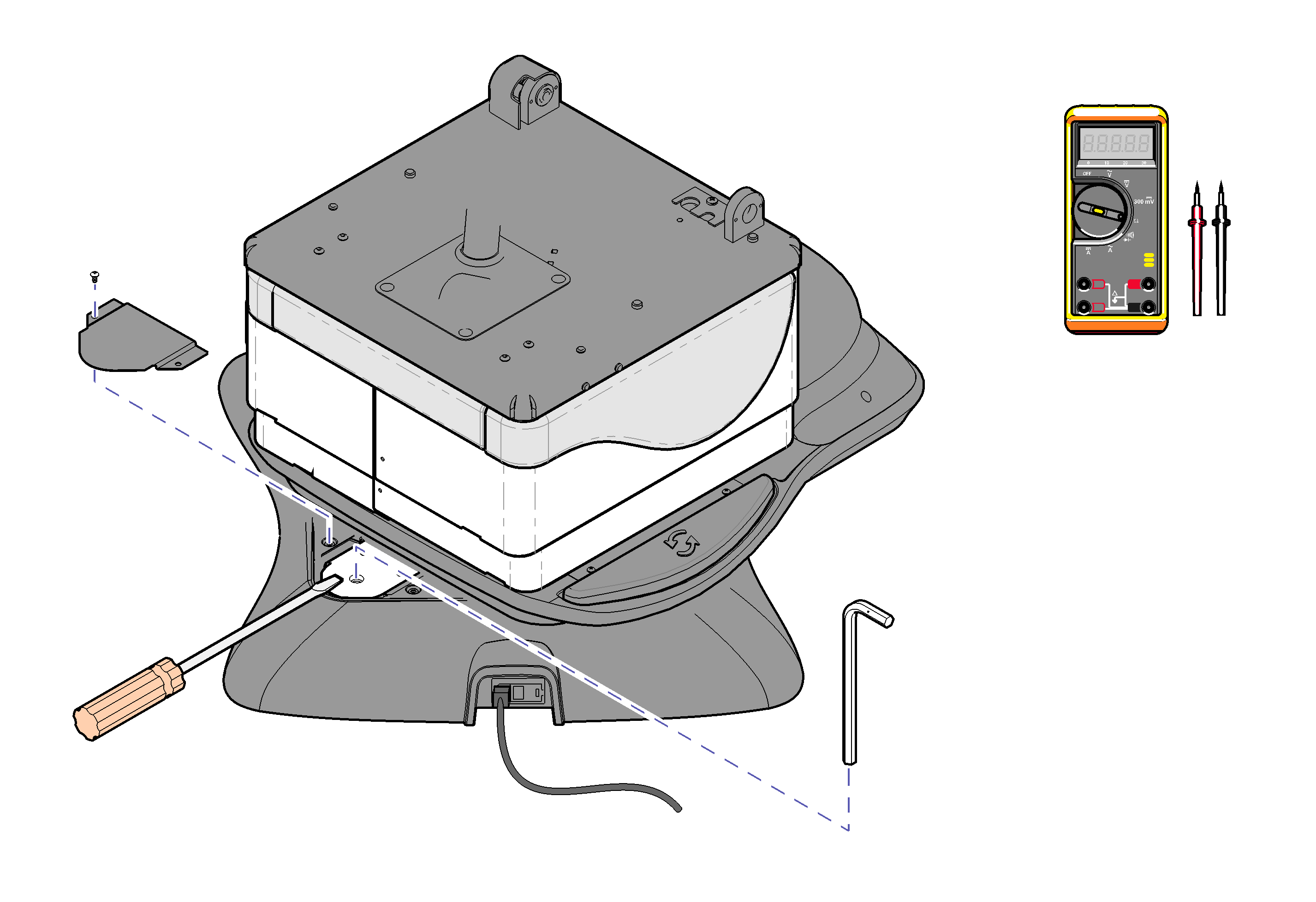
3.Check the electro-magnet. While holding a screwdriver on the brake lever, press and release the brake pedal. If you feel the magnet energize go to step 4, if not go to step 5.
4.Perform Magnet Position Adjustment. Refer to: Rotational Base Brake System
5.Check Rotational Base PC Board Fuse. If fuse is OK, perform Rotational Brake Electrical Test. Refer to: Rotational Base Brake System
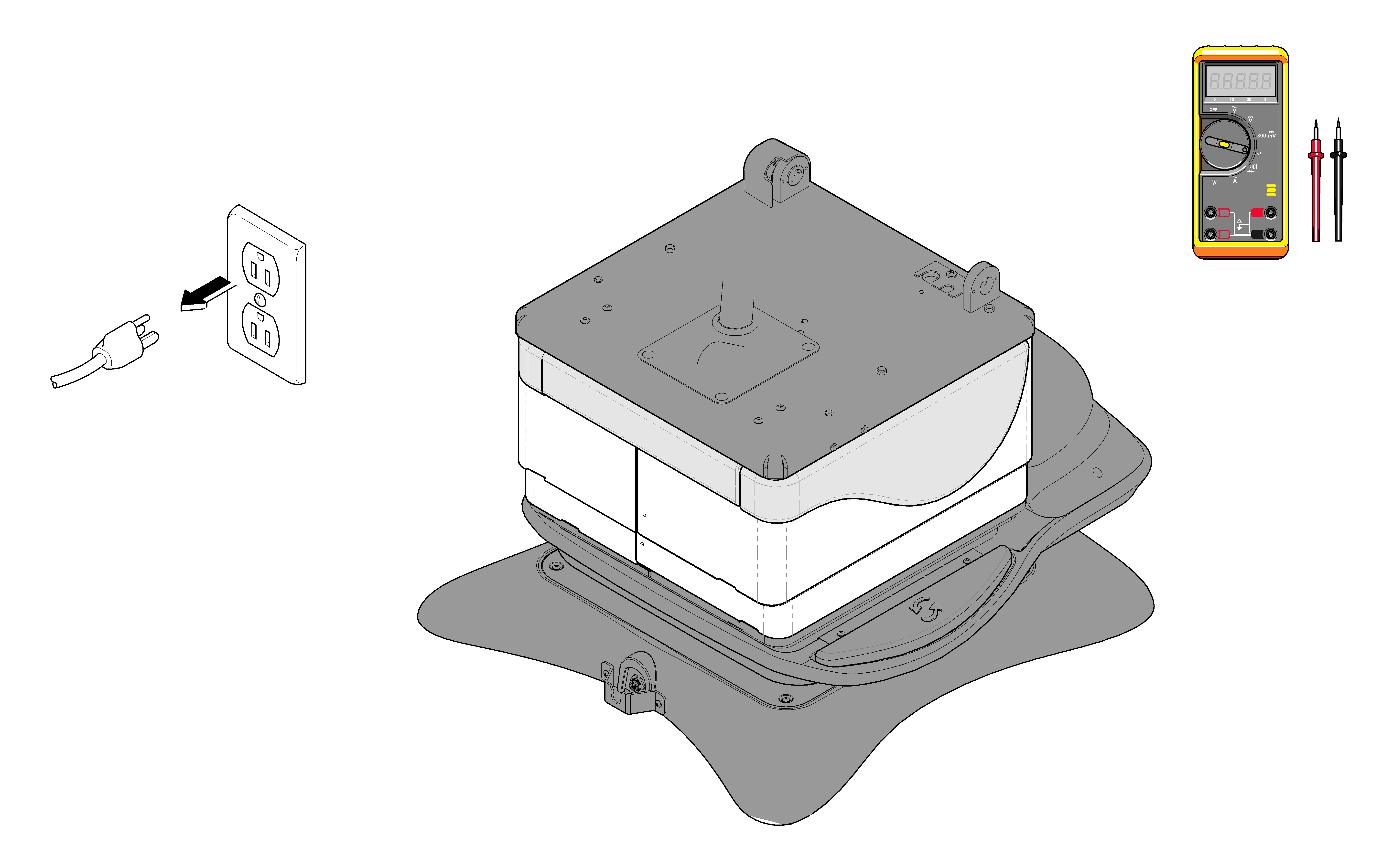
1.Unplug table power cord. If base rotation locks, go to step 2. If base does not lock, go to step 3.
2.Perform Rotational Brake Electrical Test. Refer to: Rotational Base Brake System
3.Inspect mechanical brake components. Refer to: Rotational Base Brake System
1.Debris between upper and lower castings. Without separating the base castings, remove any debris.
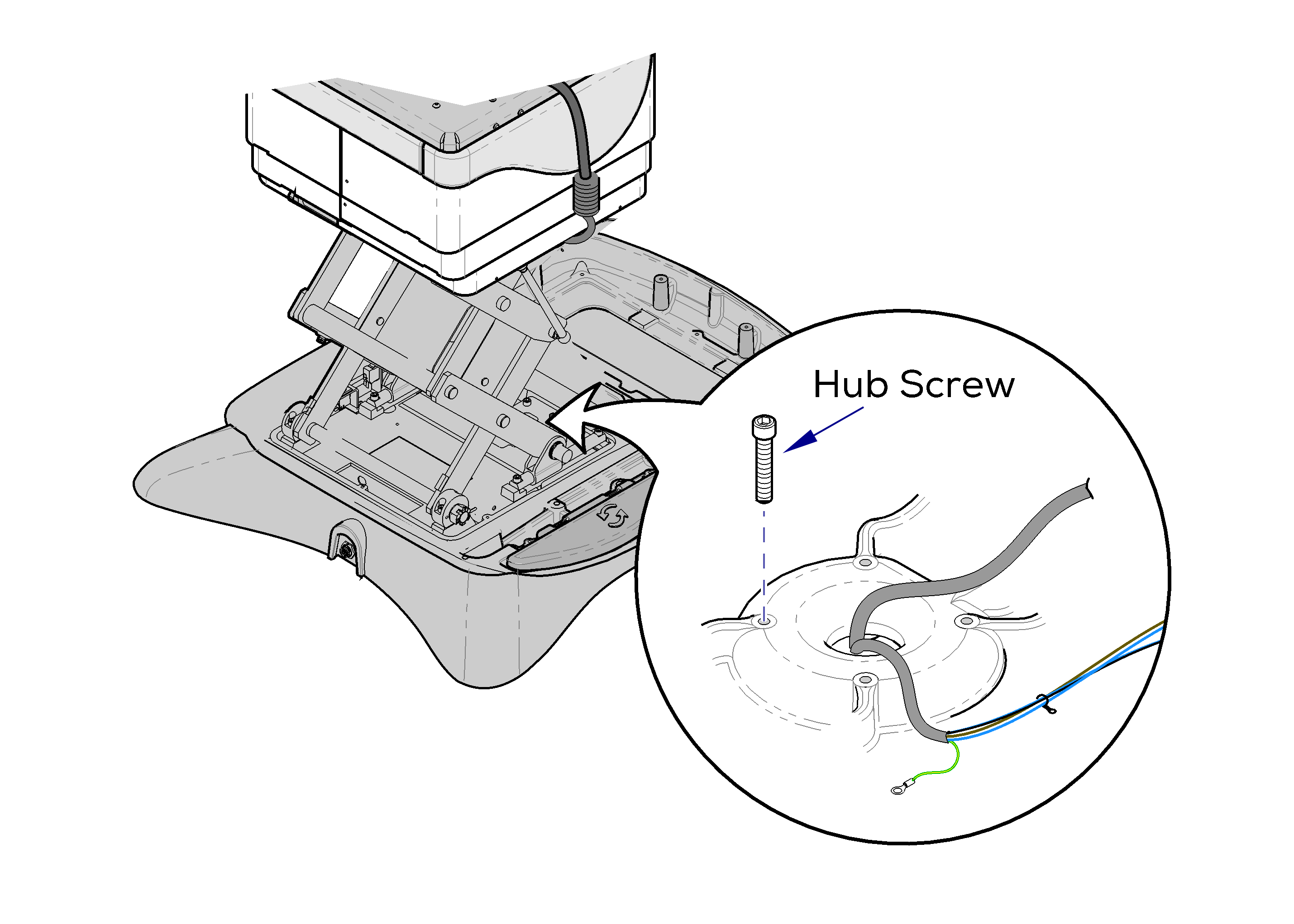
2.Loose hub screws. Tighten four screws securing the upper and lower castings. For access instructions Refer to: Rotational Base Brake System - Separating Upper and Lower Base Castings.
3.Inspect rotation bearings / brake disc. Inspect needle bearing and brake disc for damage, debris, etc. For access instructions Refer to: Rotational Base Brake System - Separating Upper and Lower Base Castings
