Biltmore/Knight Chairs Maintenance, Test and Repair
Refer to Operator Manual for complete instructions on operating the dental chair. Failure to do so could result in personal injury.
Perform an operational test on the dental chair after repair is completed to confirm repair was properly made and that all malfunctions were repaired.
Removal
1.Raise chair up to its highest position and recline the back to 45°.
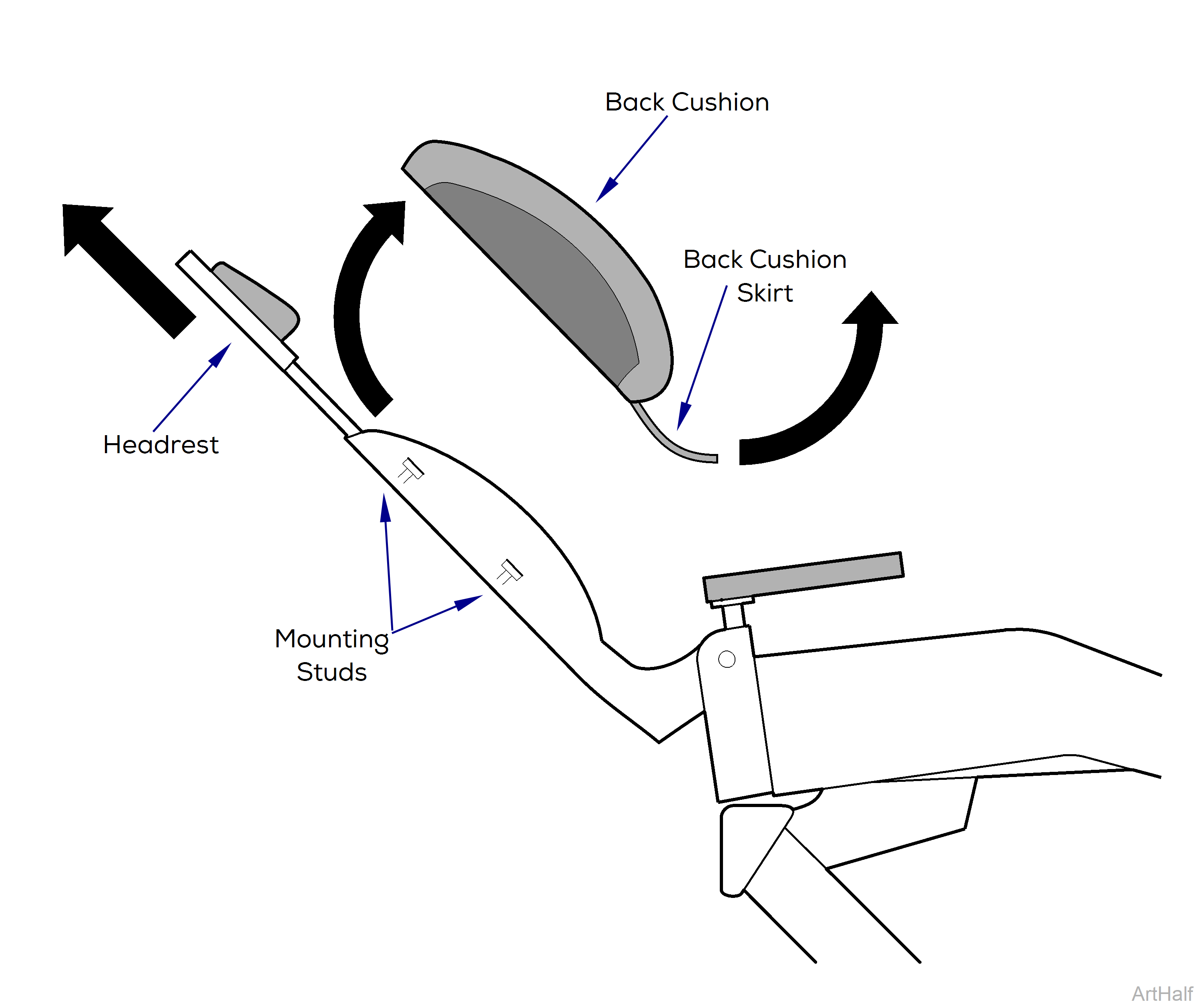
2.Move headrest assembly upward.
3.Pull upward on back cushion skirt to separate velcro on skirt from velcro on chair back.
4.Pull upward on chair back cushion to release it from mounting studs on back and remove cushion.
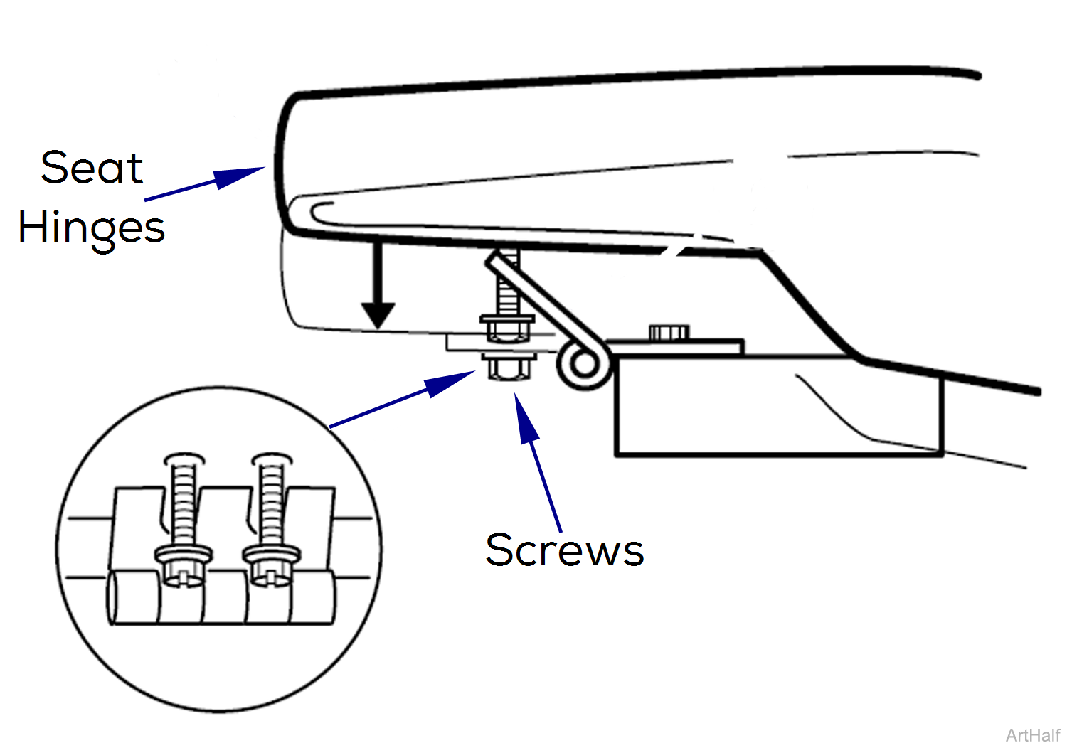
5.Using a 3/8" socket, remove four screws that secure hinges to seat cushion and remove cushion.
Installation
1.Install four screws in bottom of seat and hand tighten two turns.
2.Place two hinges up into a vertical position and lower seat cushion onto chair so it rests on hinges.
3.Rotate hinges downward toward screws allowing screws to slide into slots of hinges.
4.Tighten four screws.
Unplug chair power cord from wall outlet before removing covers or working on chair. Failure to comply could result in personal injury.
Removal
1.Unplug chair power cord.
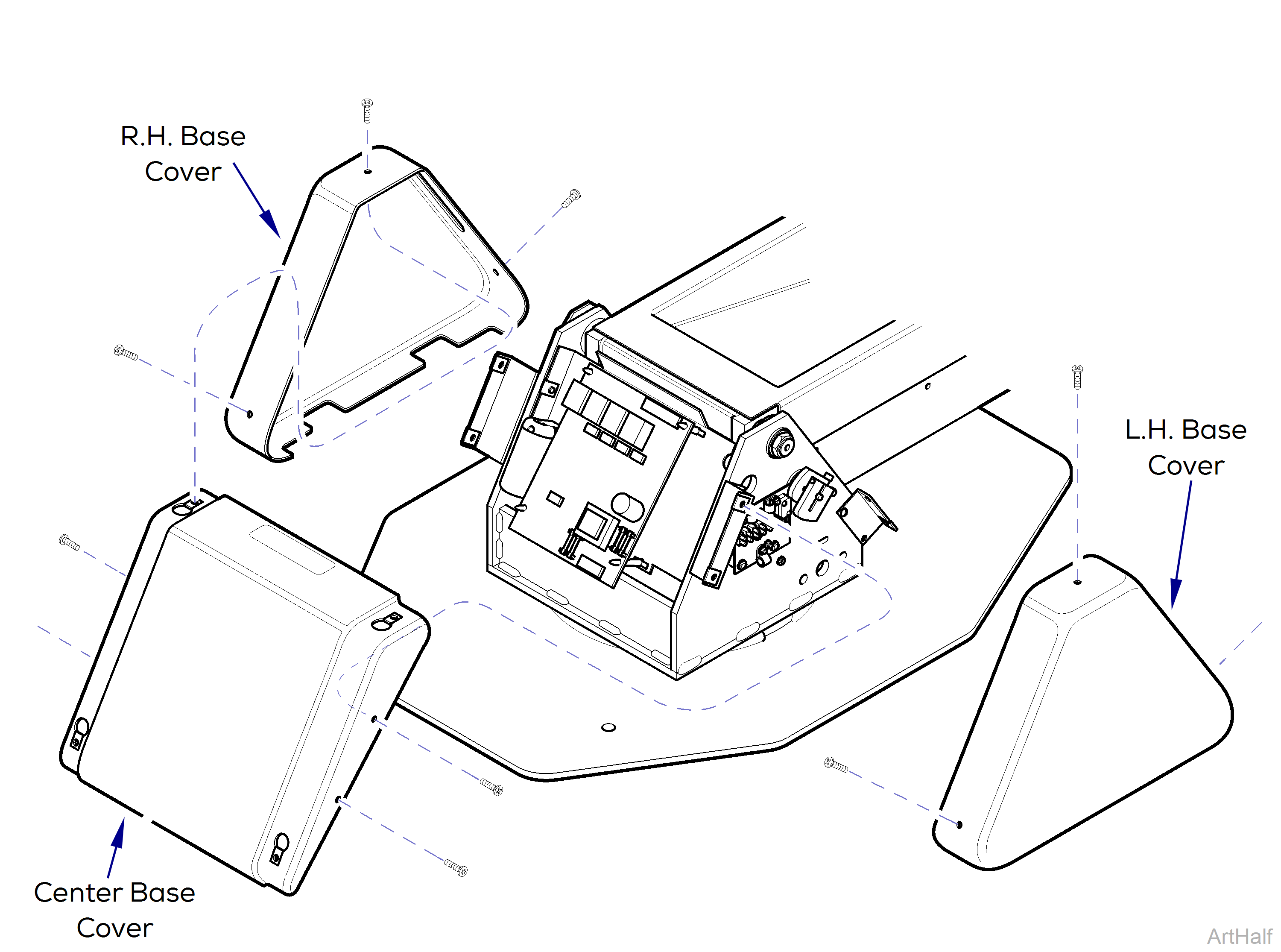
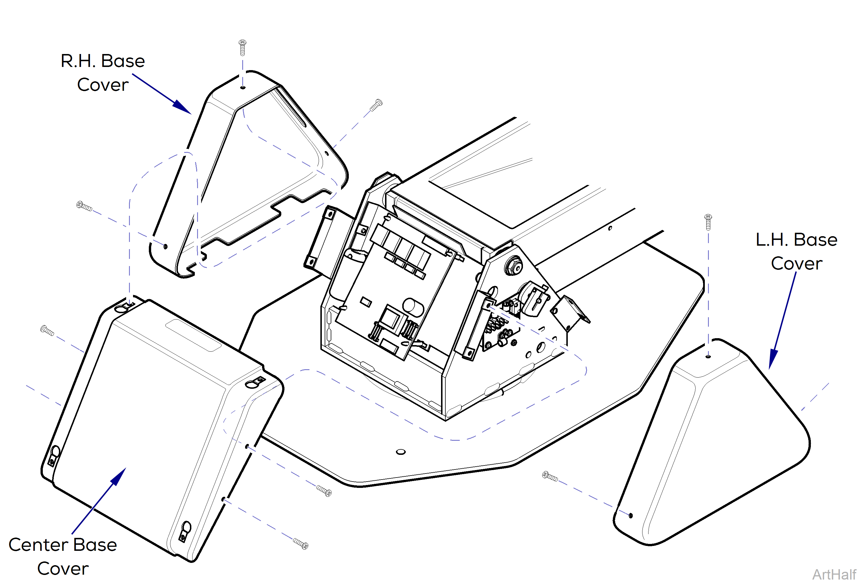
2.Remove R.H. and L.H. base covers, three screws each.
3.Remove center base cover four screws.
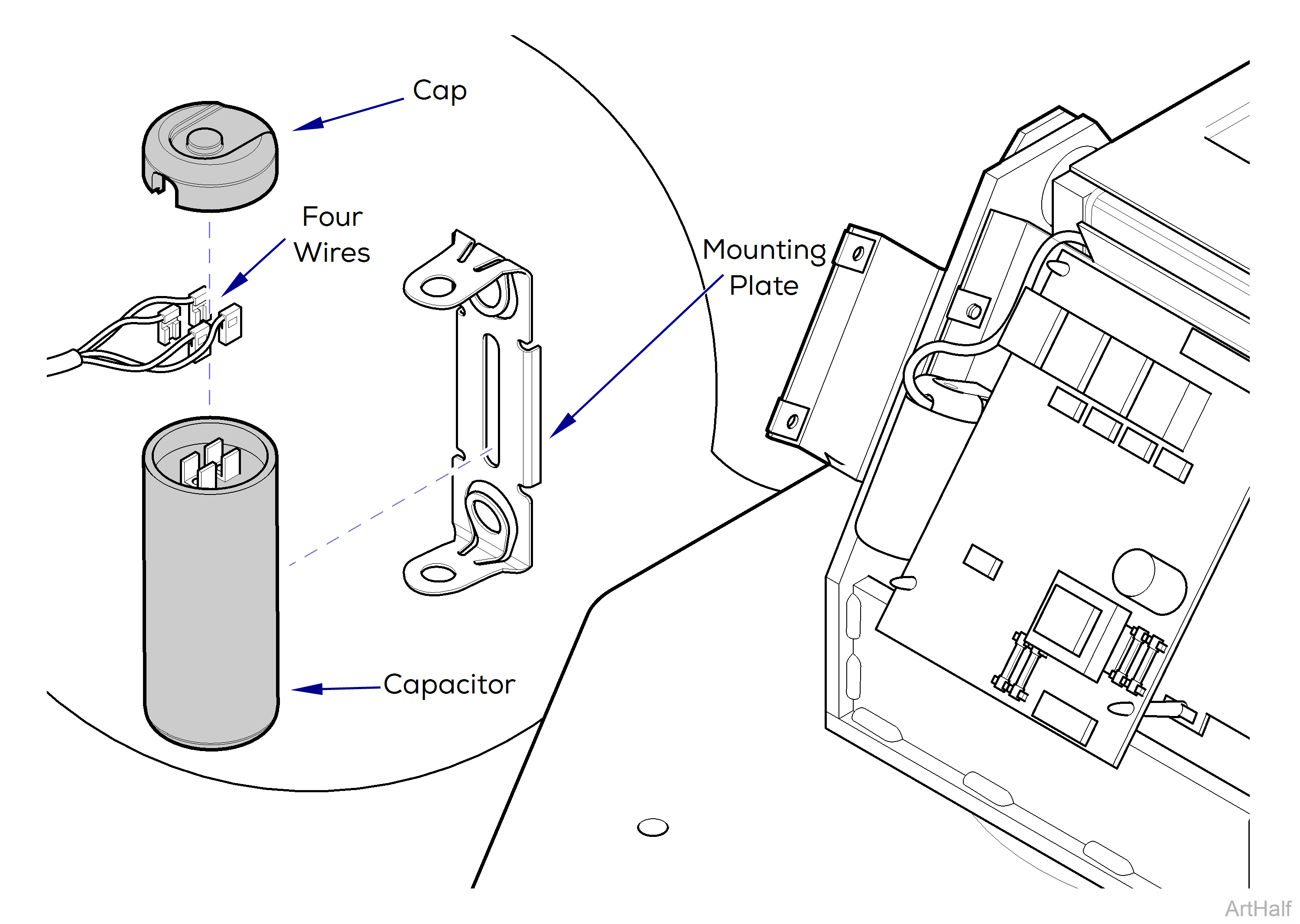
4.Using a screwdriver, pry up on tab of mounting bracket and remove capacitor.
5.Remove cap from capacitor.
Using a screwdriver with an insulated handle, jumper across capacitor terminals to discharge capacitor before touching terminals or wires. Failure to comply could result in serious personal injury.
6.Discharge capacitor.
7.Tag and disconnect four wires and remove capacitor.
Installation
1.Connect four wires to capacitor.
2.Install capacitor cap.
3.Position capacitor on mounting bracket making sure capacitor is held firmly in place with tabs of bracket.
4.Install center base cover on mounting brackets and secure with four screws.
5.Install L.H. and R.H. base cover on center base cover three screws each.
6.Plug chair power cord into wall outlet and check operation.
Rotate chair so it is aligned straight on base and engage the brake to prevent movement. If there are chair mounted accessories, assure they are folded inward, over chair, to prevent side loading during base motor removal and assembly procedures.
Removal
1.Align chair on base, engage brake, and, if necessary, fold any chair mounted accessories inward, over chair.
2.Unplug chair power cord.
3.Remove R.H. and L.H. base covers, three screws each.
4.Remove center base cover four screws.
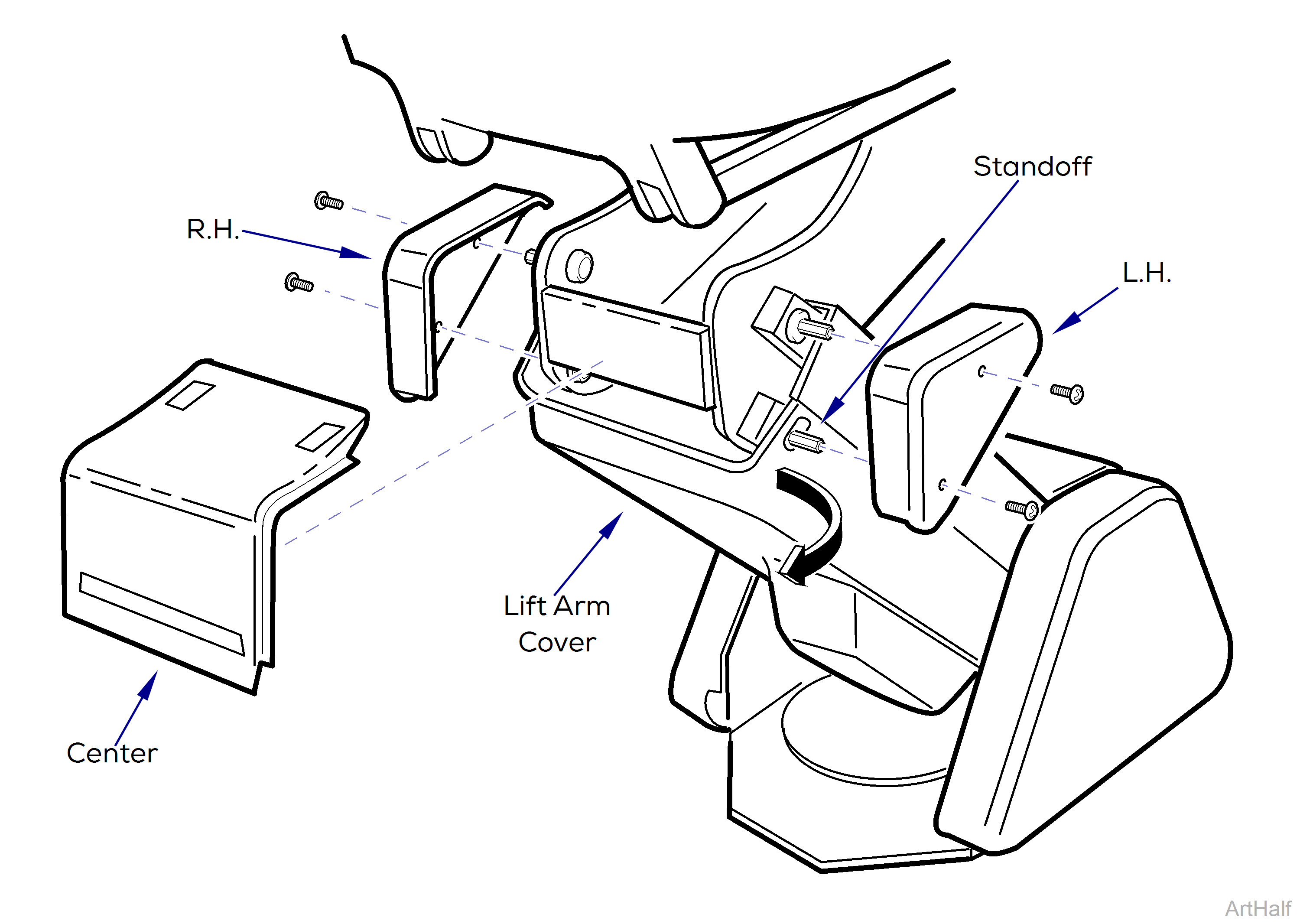
5.Remove R.H. Center and L.H. platform covers, 4 screws.
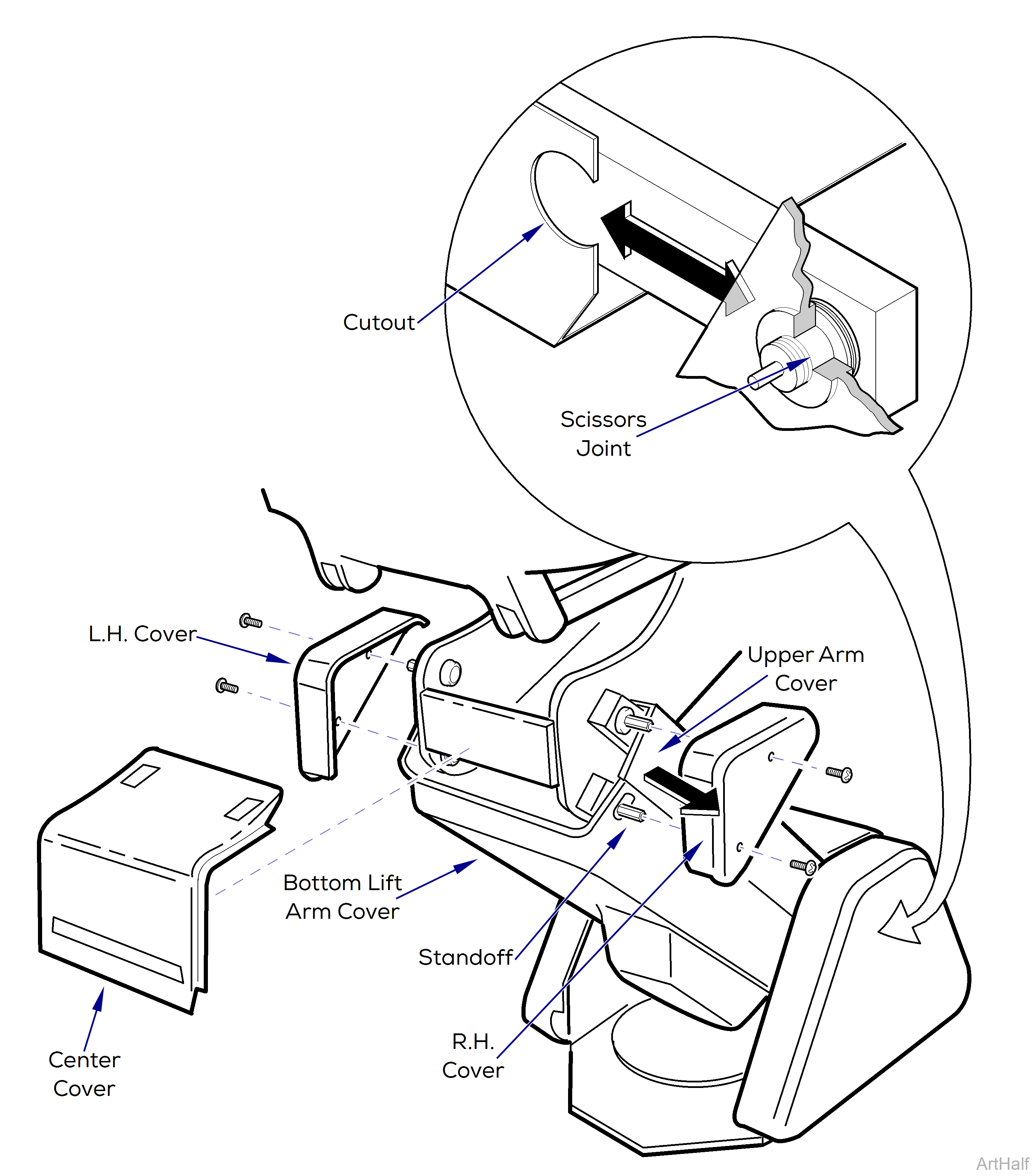
6.Pull outward on one corner of bottom lift arm cover until it clears standoff. Repeat step for other corner and remove cover.
7.If base motor is operable:
a.Plug chair power cord into wall outlet.
b.Raise BASE UP function all the way up.
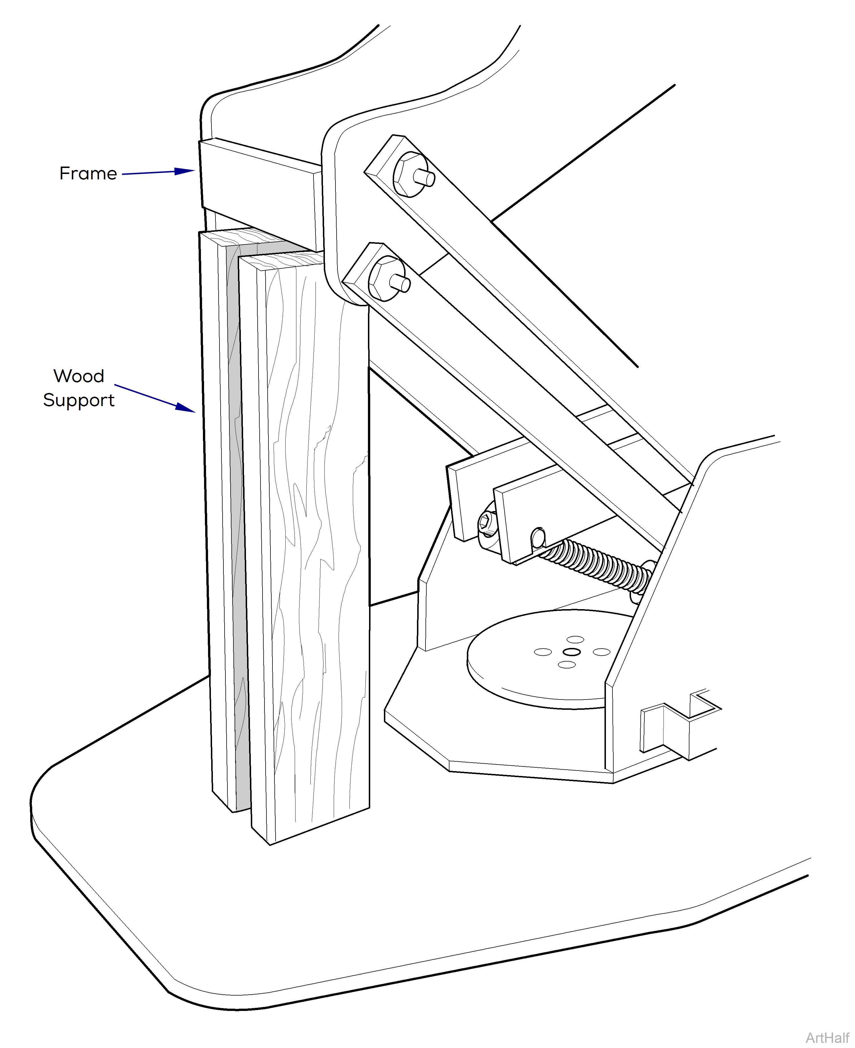
Make sure that chair top is securely supported before starting to remove base motor. Failure to do so could result in chair top collapsing which could cause serious personal injury or death.
Run base motor until top support just rests against wood supports. Do not draw chair down so base motor is binding against wood supports.
c.Position two wood 2 x 4’s (18” long [45.7 cm] ) beneath top support then lower chair so it barely rests on the wood supports..
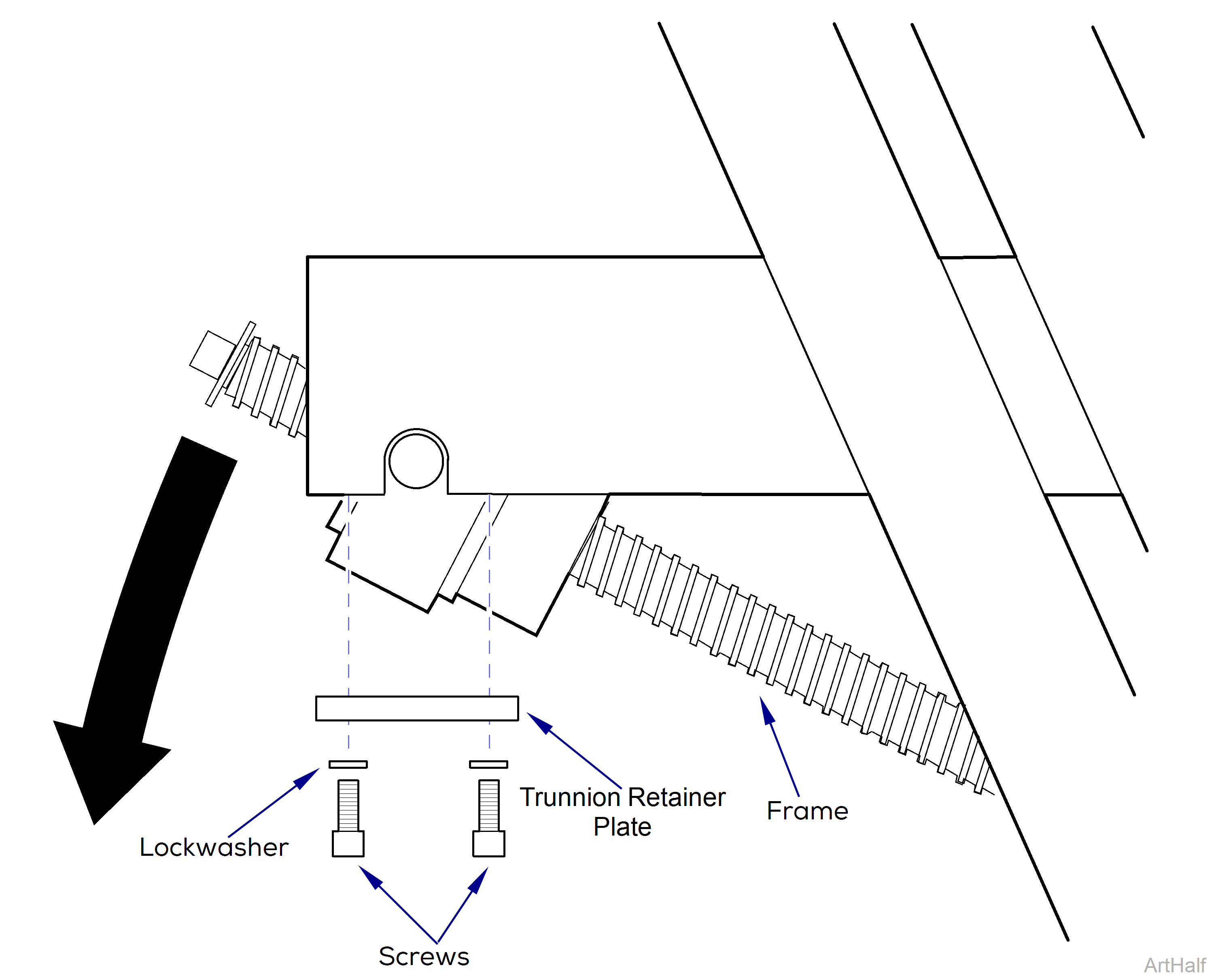
d.Remove four screws, lockwashers, and trunnion retainer plate from frame.
e.Carefully lower chair onto wood supports, until motor shaft and trunnion block disengages from frame.
Disconnect the power from the chair. Failure to comply could result in personal injury.
f.Disconnect power supply to chair.
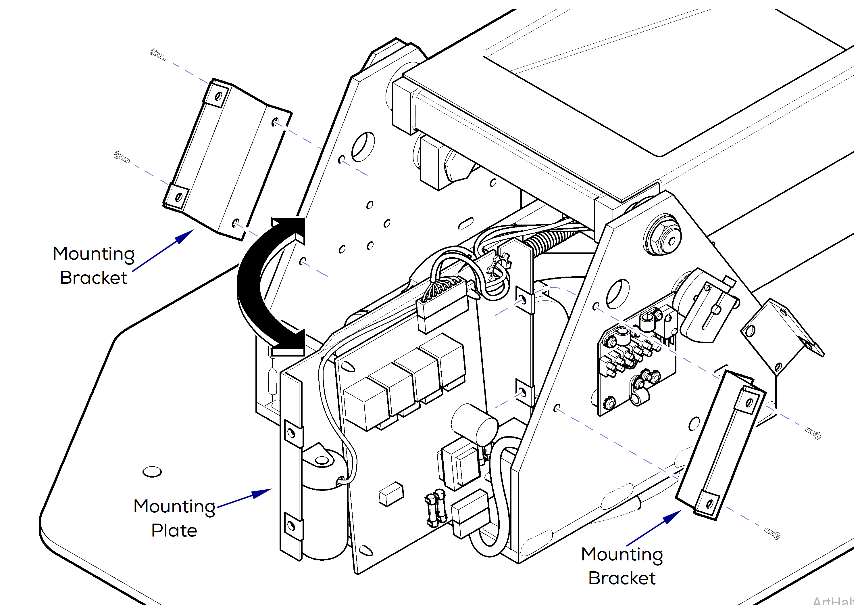
g.Remove mounting brackets, four screws.
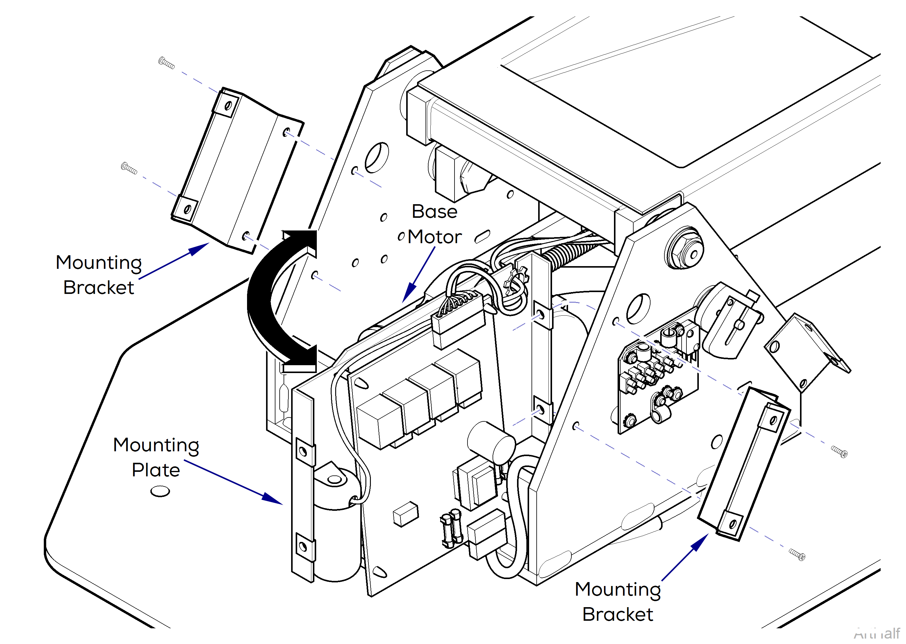
Cut any cable ties or remove any cables from cable clamps which are restricting movement of mounting plate (2) when its left side is being pulled outward.
h.Carefully pull outward on left side of mounting plate and position plate so base motor can be accessed.
i.Unplug base motor wire harness and disconnect cable clamp from base.
j.Remove one of the retaining rings and the pin securing clevis to base mounting bracket.
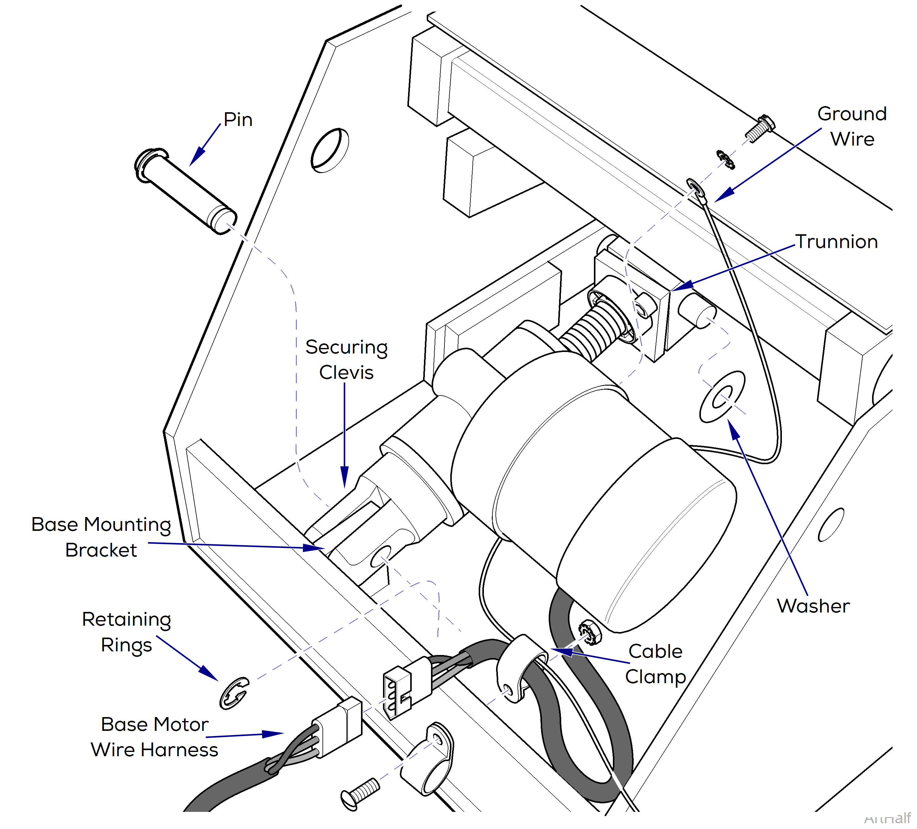
k.Remove ground wire from motor, one screw and lockwasher.
l.Remove two washer; one from each side of the trunnion
m.Remove four screws, lockwashers, and trunnion retainer plate from the frame, then remove motor assembly.
8.If base motor is not operable:
Disconnect the power from the chair. Failure to comply could result in personal injury.
a.Disconnect power supply to chair.
b.Remove mounting brackets, four screws.
Cut any cable ties or remove any cables from cable clamps which are restricting movement of mounting plate when its left side is being pulled outward.
c.Carefully pull outward on left side of mounting plate and position plate so base motor can be accessed.
d.Unplug base motor wire harness and disconnect cable clamp from base.
e.Remove one of the retaining rings and the pin securing clevis to base mounting bracket.
f.Remove ground wire from motor, one screw and lockwasher.
g.Remove two washers; one from each side of trunnion.
Make sure that chair top is securely supported before starting to remove base motor. Failure to do so could result in chair top collapsing which could cause serious personal injury or death.
Do not apply pressure to top support with jack until after base motor has been disconnected from base mounting bracket or damage could occur to motor assembly.
h.Place a jack beneath top support to support it while removing base motor.
i.Using jack, elevate chair to access shaft end of motor assembly.
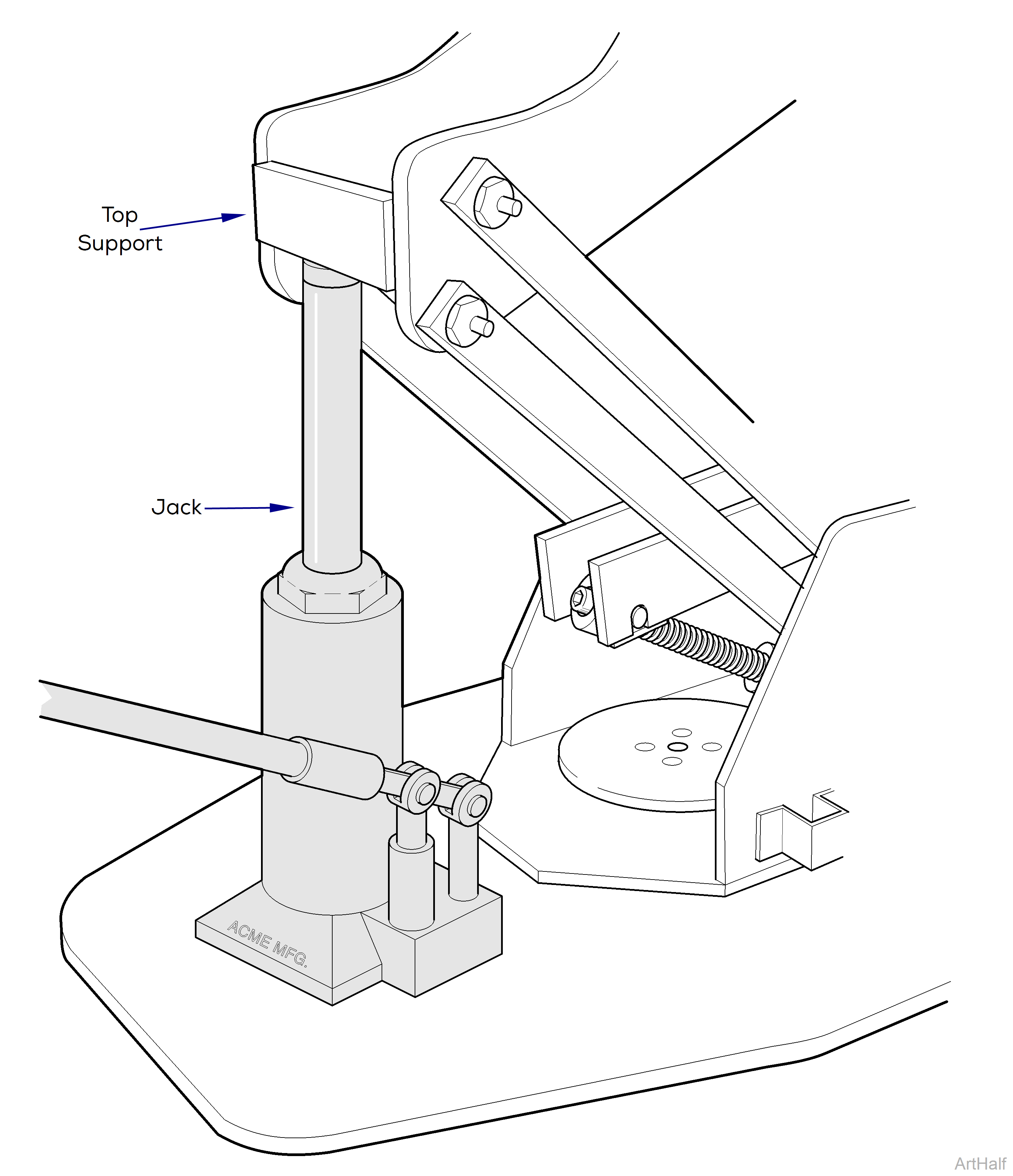
j.Remove four screws, lockwashers, and trunnion retainer plate from the frame, then remove motor assembly.
Installation
1.Install two nylon washers; one on each side of trunnion.
If new base motor comes with a ground wire, remove it and use the existing ground wire on chair.
2.Attach ground wire to base motor (one screw and washer).
3.Attach clevis of base motor to mounting bracket with pin and two retaining rings.
4.Connect base motor wire harness to wire harness.
5.Install cable clamp (one screw and nut).
6.Place PC board mounting plate back in position and install mounting brackets (four screws).
Carefully jog BASE UP so trunnion moves just enough to insert into slot of support bracket. Do not remove wood supports until trunnion brackets have been securely installed.
7.Carefully jog BASE UP function while guiding trunnion arms into trunnion slots. Make sure trunnion arms are fully seated in trunnion slots.
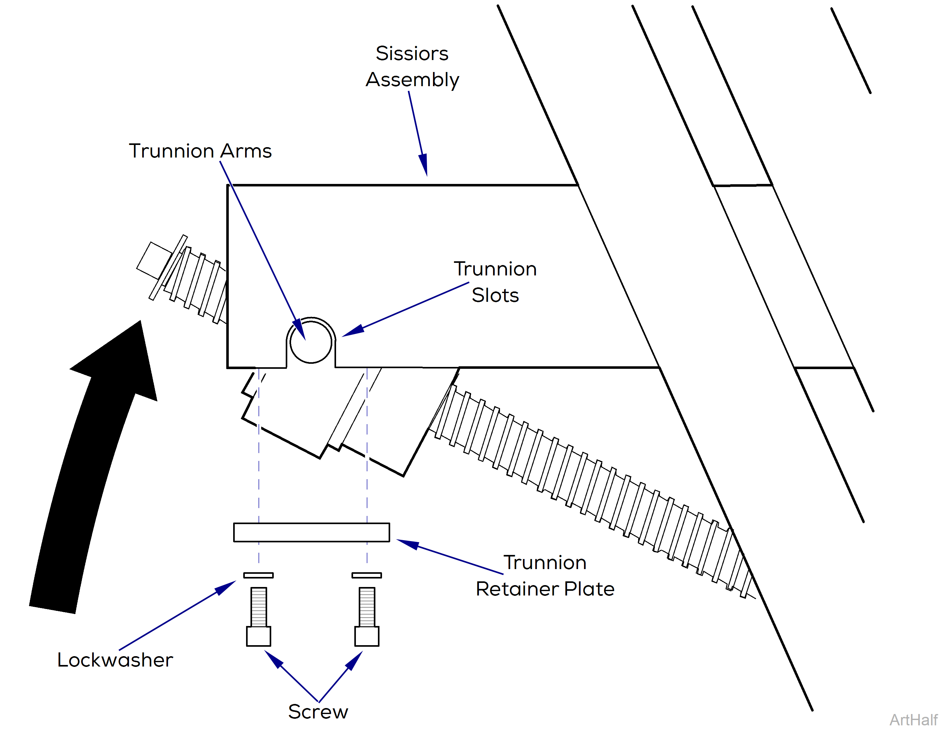
8.Install trunnion retainer plate on scissors assembly and secure with four lockwashers and screws.
9.Raise BASE UP function all the way up and remove wood supports.
10.Pull outward on one corner of upper arm cover; then install bottom lift arm cover on standoff, making sure cutout is mounted on scissors joint. Repeat step for other corner of bottom lift cover.
11.Install center, R.H. and L.H. platform covers (four screws).
12.Install center base cover (four screws).
13.Install R.H. and L.H. base covers (six screws).
14.Plug chair power cord into wall outlet.
Removal
1.Remove base motor.
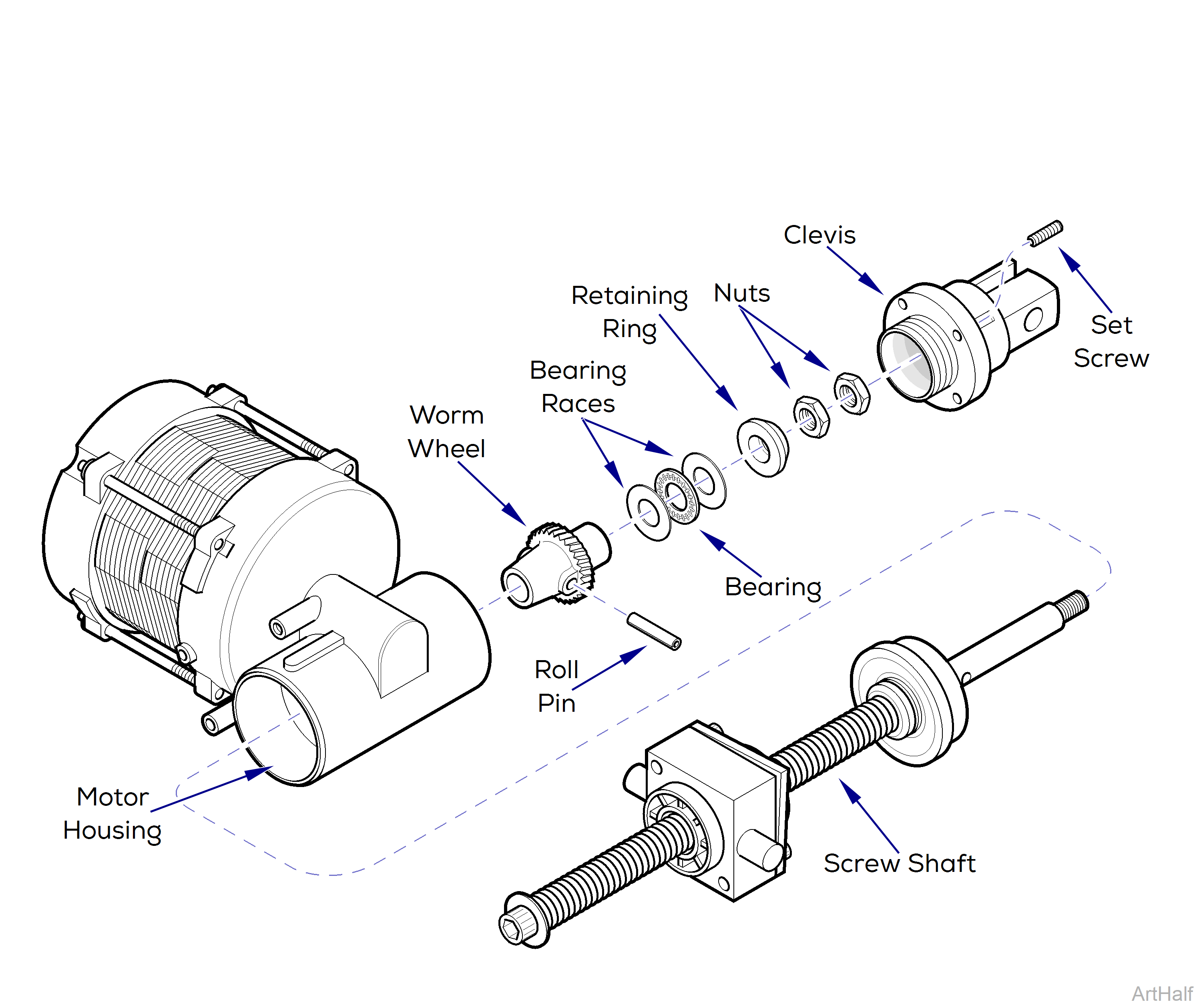
2.Using a 3mm Allen Wrench, remove two setscrews and then unscrew clevis from motor housing.
3.Remove two nuts from screw shaft.
4.Using a rubber mallet, gently drive screw shaft out of motor housing.
5.Remove retaining ring, two bearing races, and bearing from motor housing.
6.Using a 3/16” punch and hammer, drive out roll pin and remove worm wheel from screw shaft.
7.Inspect inside motor housing for broken worm wheel pieces, metal shavings, or any other foreign debris. Remove any debris. Inspect screw shaft for burrs. Remove any burrs with a file.
Installation
1.Install worm wheel on screw shaft and then, using a hammer and 3/16” punch, secure with roll pin, making sure ends of roll pin are flush with worm wheel.
There may be excess grease in the motor housing which may be used for the following step.
2.Coat surfaces of two bearing races, bearing, and worm wheel with high temperature bearing grease.
3.Insert screw shaft into motor housing as far as possible by hand. Then, using a rubber mallet, gently tap screw shaft in until fully seated in motor housing.
4.Install one bearing race, bearing, one bearing race, and retaining ring on end of screw shaft.
5.Coat threads of two nuts with removable thread locking adhesive (Loctite 242).
Do not over-tighten lock nuts on screw shaft.
6.Install first nut on screw shaft and tighten until finger tight. Then, using a wrench, tighten nut 1/4 additional turn.
7.Install second nut on screw shaft until finger tight. Then, while holding first nut in place, tighten second nut against first nut.
8.Screw clevis into motor housing and tighten until finger tight. Then, unscrew clevis slightly until the next closest two setscrew holes are aligned with setscrew holes on motor housing. Secure clevis in this position with two setscrews.
9.Install base motor.
Removal
1.Remove the base motor.
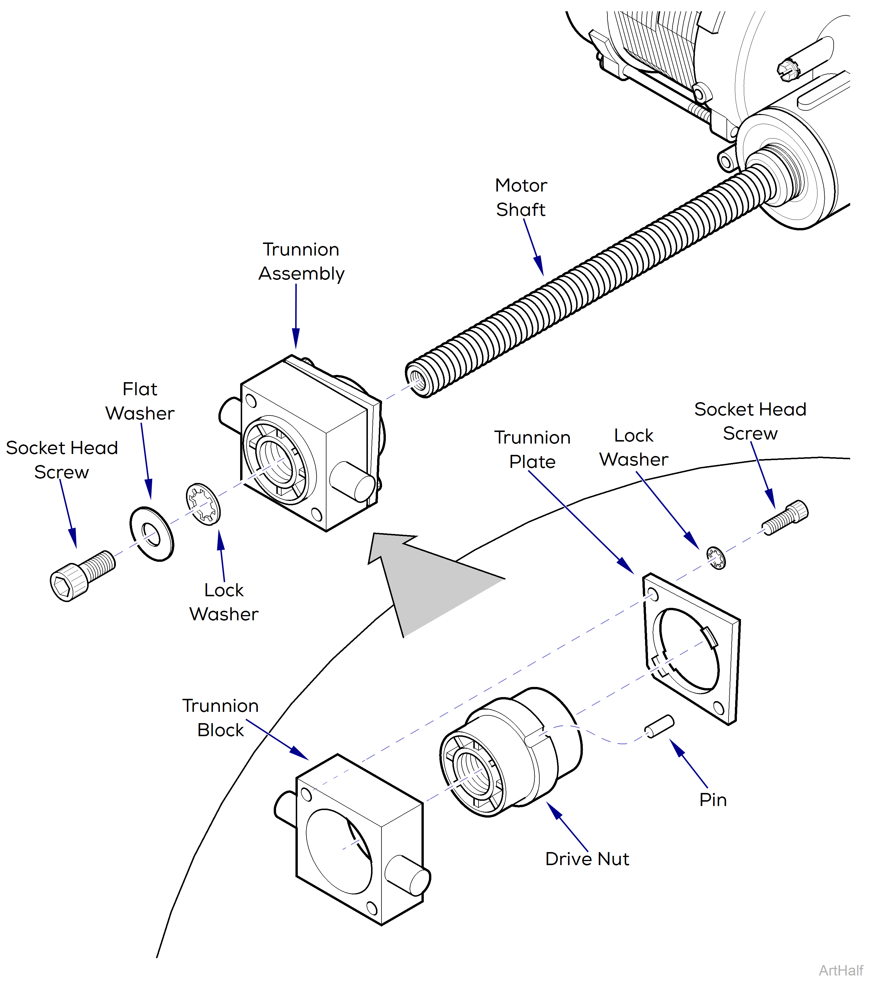
2.Using an 8mm Allen wrench, remove the socket head screw, flat washer, and lock washer from motor shaft.
3.Unscrew the trunnion assembly from the motor shaft.
Disassembly
1.Using a 3/16” allen wrench, remove the two socket head set screws and lock washers and remove the trunnion plate.
2.Separate the drive nut, pin and, trunnion block.
Assembly
1.Place the drive nut into the trunnion block and install the pin.
The trunnion plate is intentionally deformed in order to apply pressure to the drive nut.
2.Place trunnion plate onto trunnion block and secure with two socket head screws and lock washers.
Installation
Trunnion plate must face toward the motor when installing trunnion assembly on motor shaft.
1.Install trunnion assembly on motor shaft.
2.Install trunnion assembly on motor shaft.
Lubricate both studs on trunnion block and motor shaft with an extreme pressure lubricant such as Magnalube-G Teflon Lubricant or equivalent.
3.Install base motor.
Removal
1.Unplug chair power cord.
2.Remove seat upholstery by loosening four screws that secure seat upholstery to seat hinges.
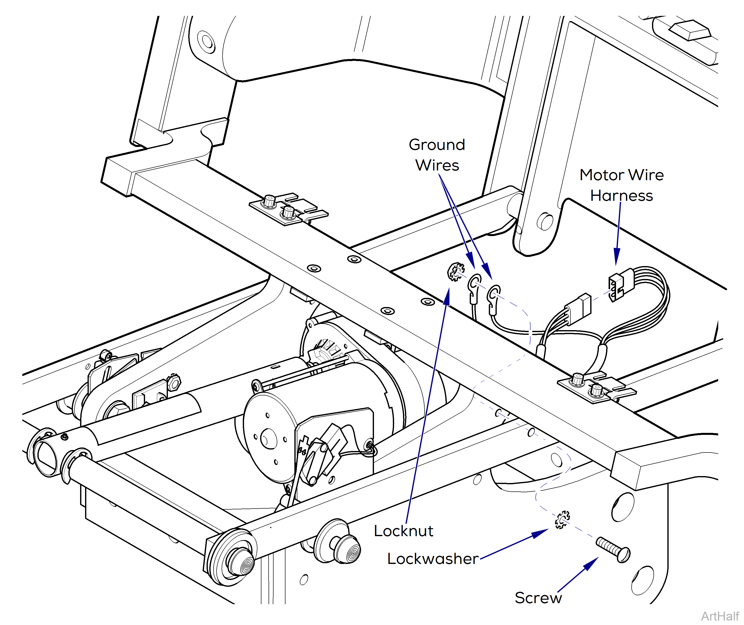
3.Disconnect motor wire harness from wire harness.
4.Remove two ground wires by removing locknut, screw and lockwasher from frame.
Be sure Back section is supported before disconnecting Back Motor assembly. Failure to comply may result in personal injury.
5.While supporting back section, remove two push nut caps, two leg support rollers, two small retaining rings, and two large E-clips on tow bar shaft.
6.Loosen set screw that secures motor actuator tube to tow bar shaft.
7.Separate tow bar shaft from seat support bar assemblies.
8.While supporting back motor assembly, remove four screws and lock washers and remove back motor assembly.
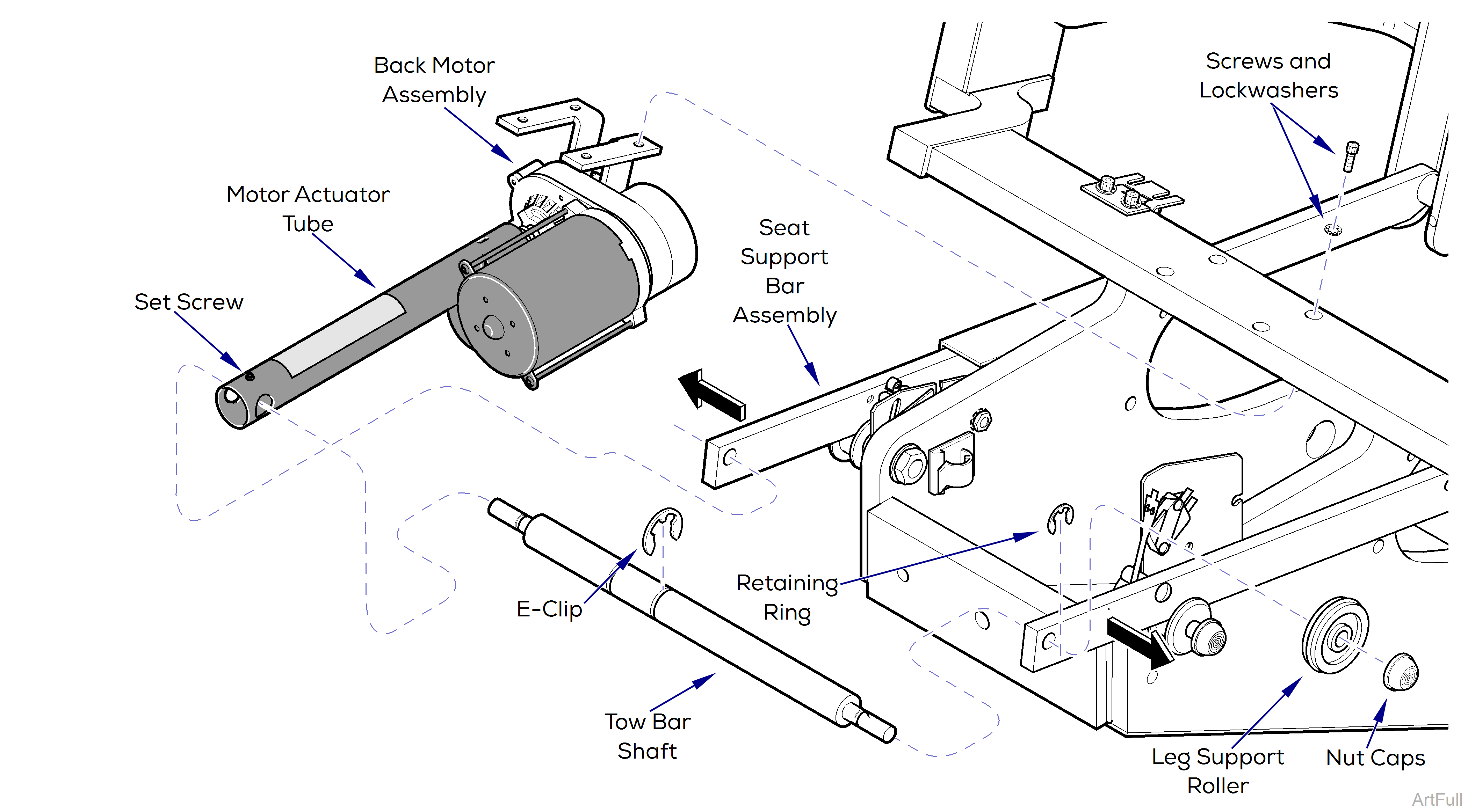
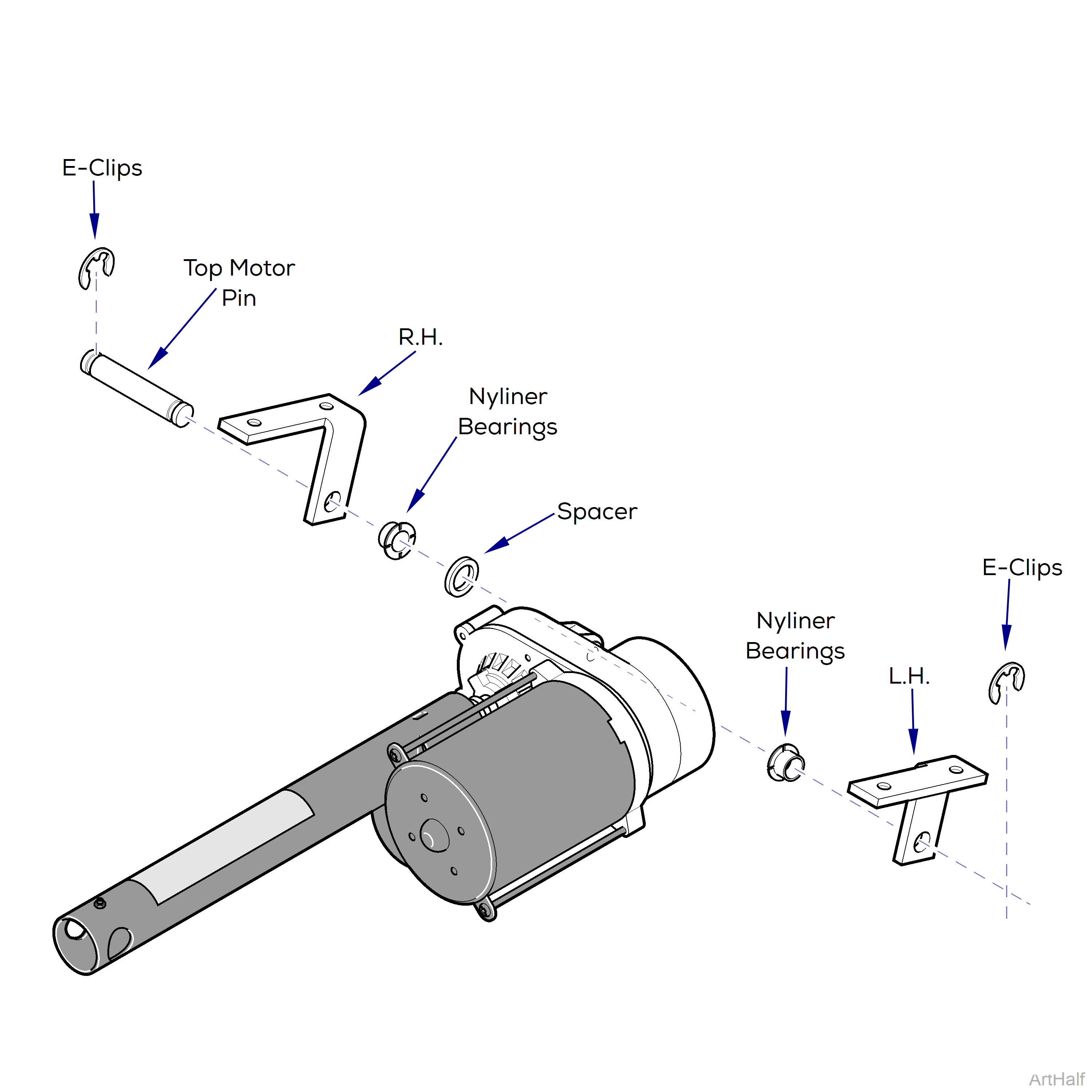
9.Remove two E-clips, top motor pin, spacer, and R.H. and L.H. motor mount brackets.
Installation
Assure R.H. and L.H. motor mount brackets are positioned correctly on motor during installation. Spacer can be installed on either side of bracket of motor. If necessary, install new nyliner bearings in mounting brackets.
1.Place R.H. and L.H. motor mount brackets in position and install top motor pin, spacer and E-clips
2.Connect motor wire harness to mating chair wire harness.
3.Plug chair power cord into wall outlet receptacle.
4.Run BACK UP function until back motor is stopped by motor’s internal limit switch.
5.Unplug chair power cord.
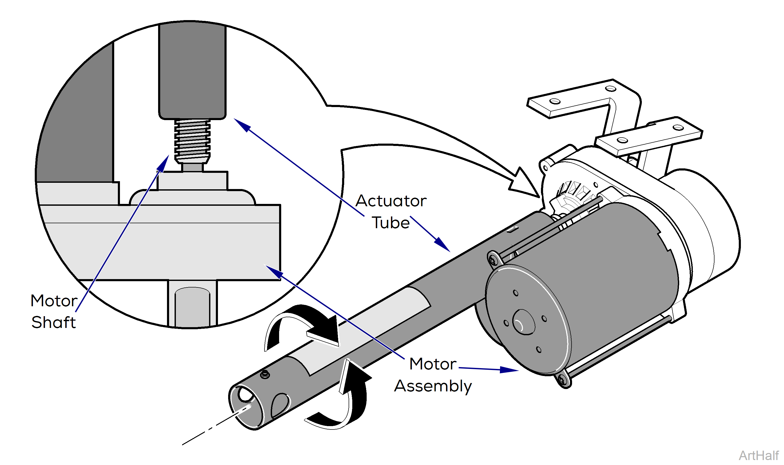
When adjusting distance between actuator tube and motor assembly do not turn motor shaft.
6.Manually adjust actuator tube by rotating it toward motor assembly until 5 threads on motor shaft are visible.
7.Position motor assembly in chair and connect two ground wires to frame with lockwasher, screw, and locknut.
8.Supporting motor assembly, secure motor brackets to chair support with four screws and lockwashers.
Hole for set screw, on end of actuator tube, must be facing upward for access during installation.
9.Slide tow bar shaft thru hole on end of actuator tube.
10.Insert ends of tow bar shaft into holes on ends of seat support bar assemblies and install small retaining rings.
11.Install large E-clips on both sides of actuator tube and tighten set screw and lock nut.
Check condition of O-rings on leg support rollers and replace them if necessary.
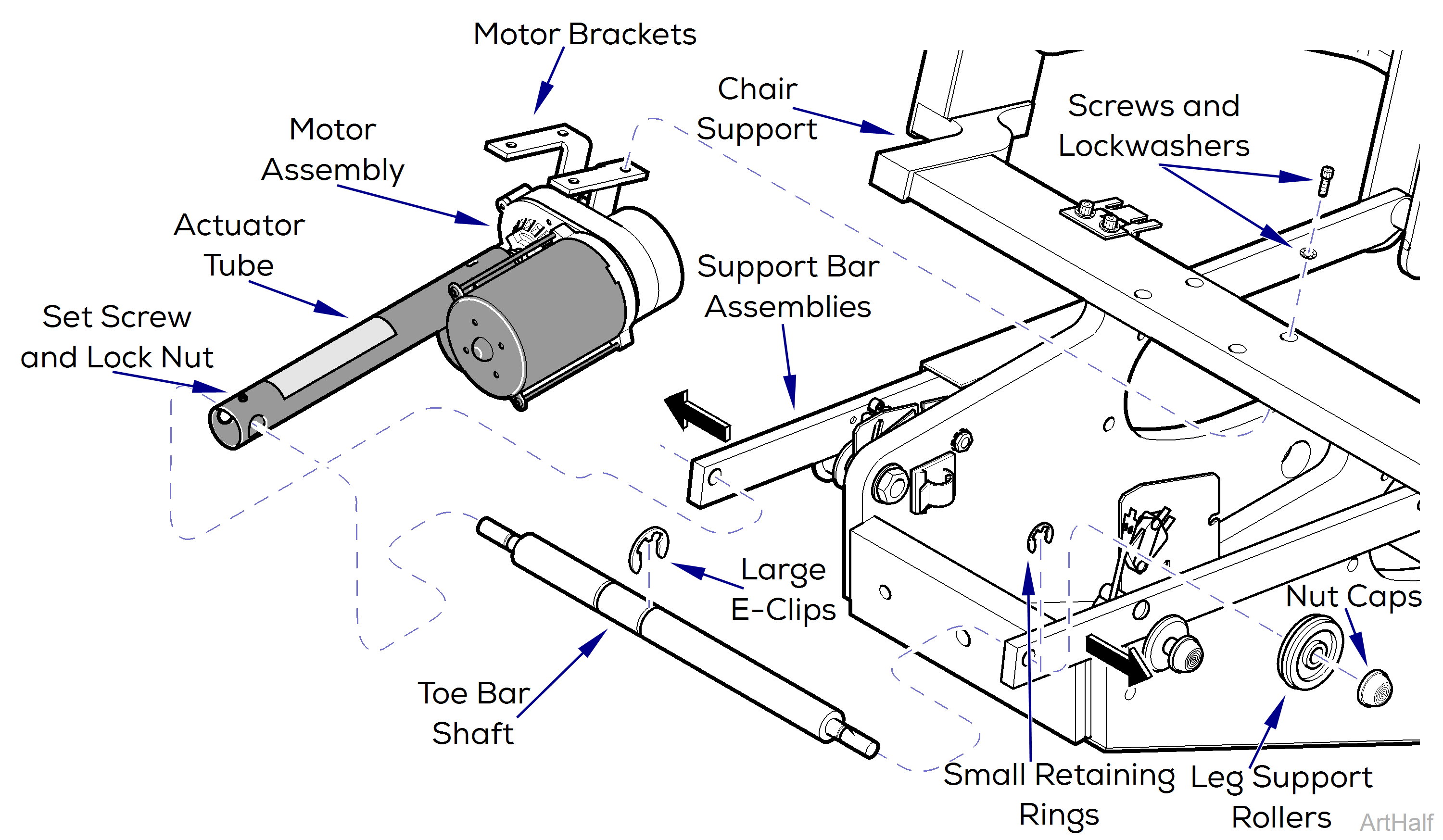
12.Lubricate both ends of tow bar shaft and install leg support rollers and push nut caps.
Assure all electrical leads are secured in existing cable clamps to prevent accidental cutting when chair is in operation.
13.Plug the chair into outlet and check operation.
Check to assure the internal motor limit switches (Back Up and Back Down) function correctly, stopping the motor at its extreme limits.
14.Install upholstery
Removal
1.Remove Base Motor
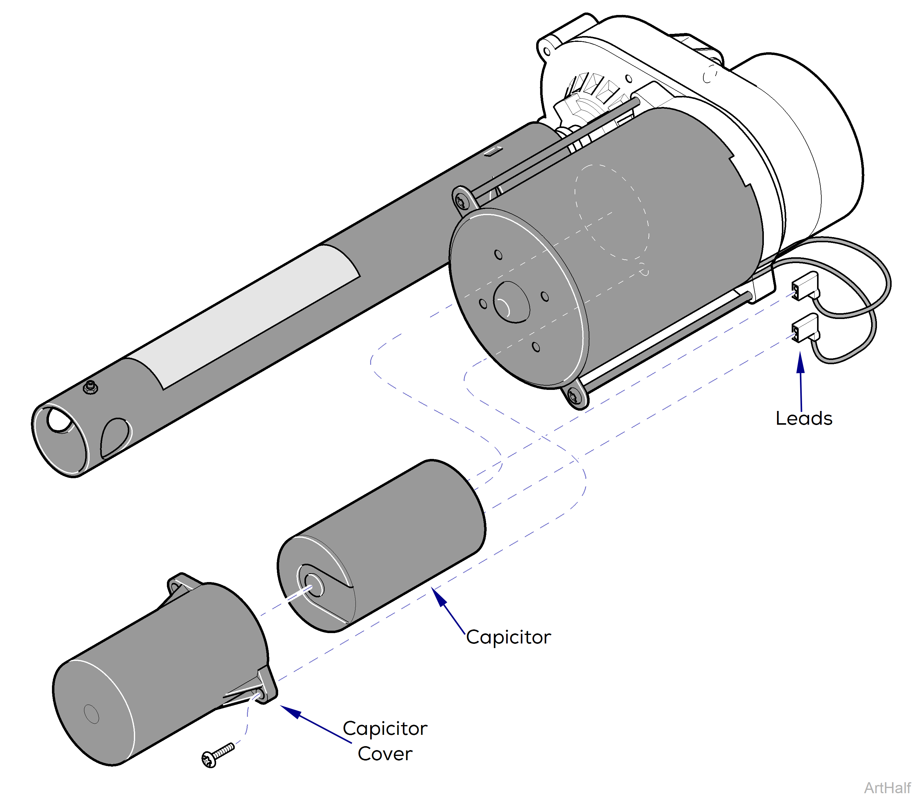
2.Remove capacitor cover, two screws.
Using a screwdriver with an insulated handle, jumper across capacitor terminals to discharge capacitor before touching terminals or wires. Failure to comply could result in serious personal injury.
3.Discharge capacitor.
4.Disconnect leads and remove capacitor.
Installation
Assure capacitor being installed is of same microfarad (Mfd) and voltage rating as one being replaced.
1.Connect electrical leads to capacitor.
2.Insert capacitor into capacitor cover and secure to base motor, two screws.
3.Install Back Motor assembly on chair.
Removal
1.Unplug chair power cord.
2.Remove R.H. and L.H. base covers, three screws each.
3.Remove center base cover, four screws.
4.Tag and disconnect foot control harness and membrane panel harness from PC circuit board.
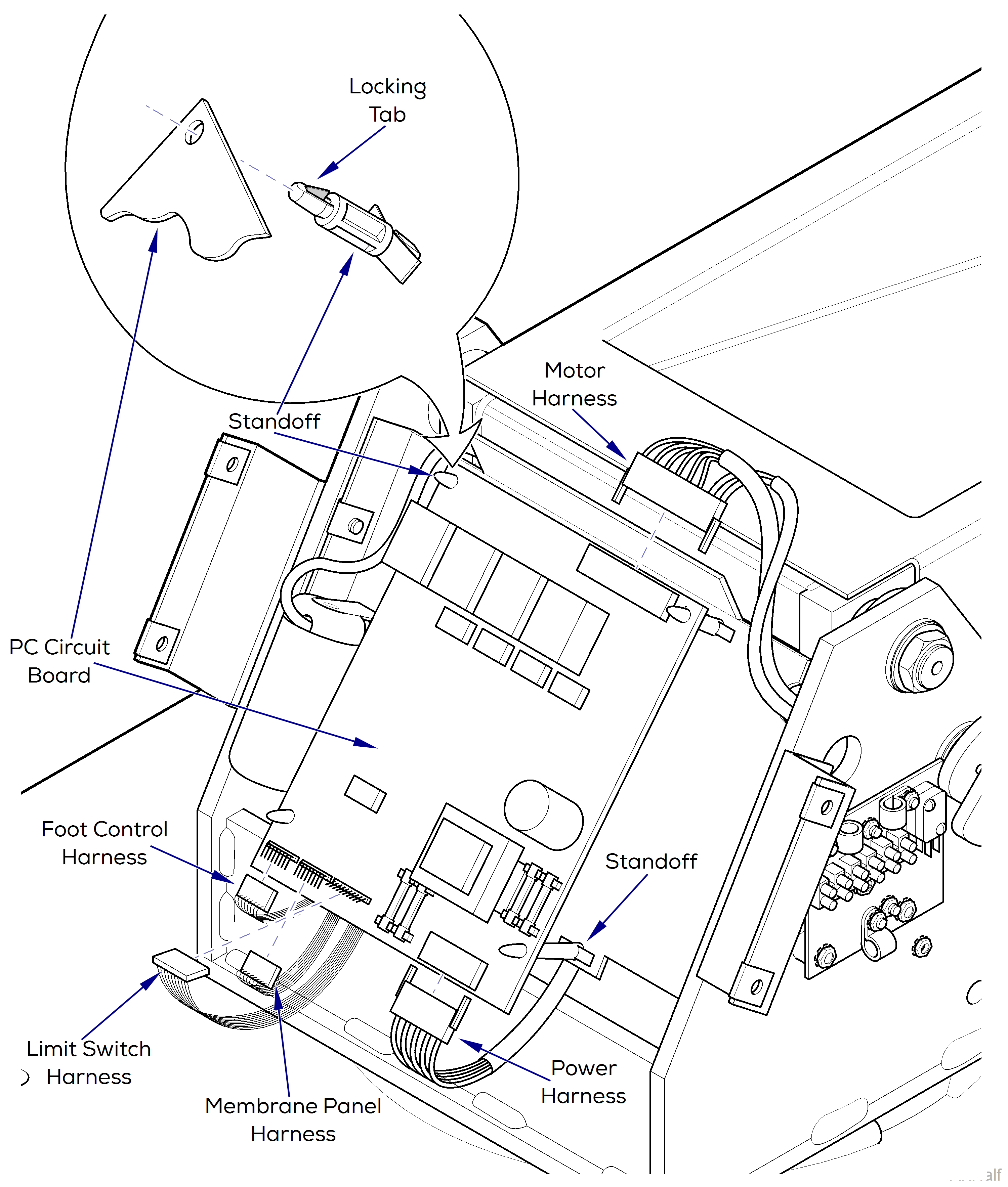
5.Disconnect limit switch harness, power harness, and motor harness from PC circuit board.
6.Using a screwdriver, depress locking tab of standoff while pulling upward on that corner of PC circuit board to release it. Repeat for three remaining standoffs and remove PC circuit board.
Installation
1.Inspect standoffs and replace them if broken.
2.Place PC board in position on standoffs, pushing down to lock in place.
3.Reconnect harnesses to their respective pin connections on PC board.
4.Install center base cover on mounting brackets and secure with four screws.
5.Install L.H. and R.H. base cover on center base cover three screws each.
6.Plug chair power cord into wall outlet and check operation.
Removal
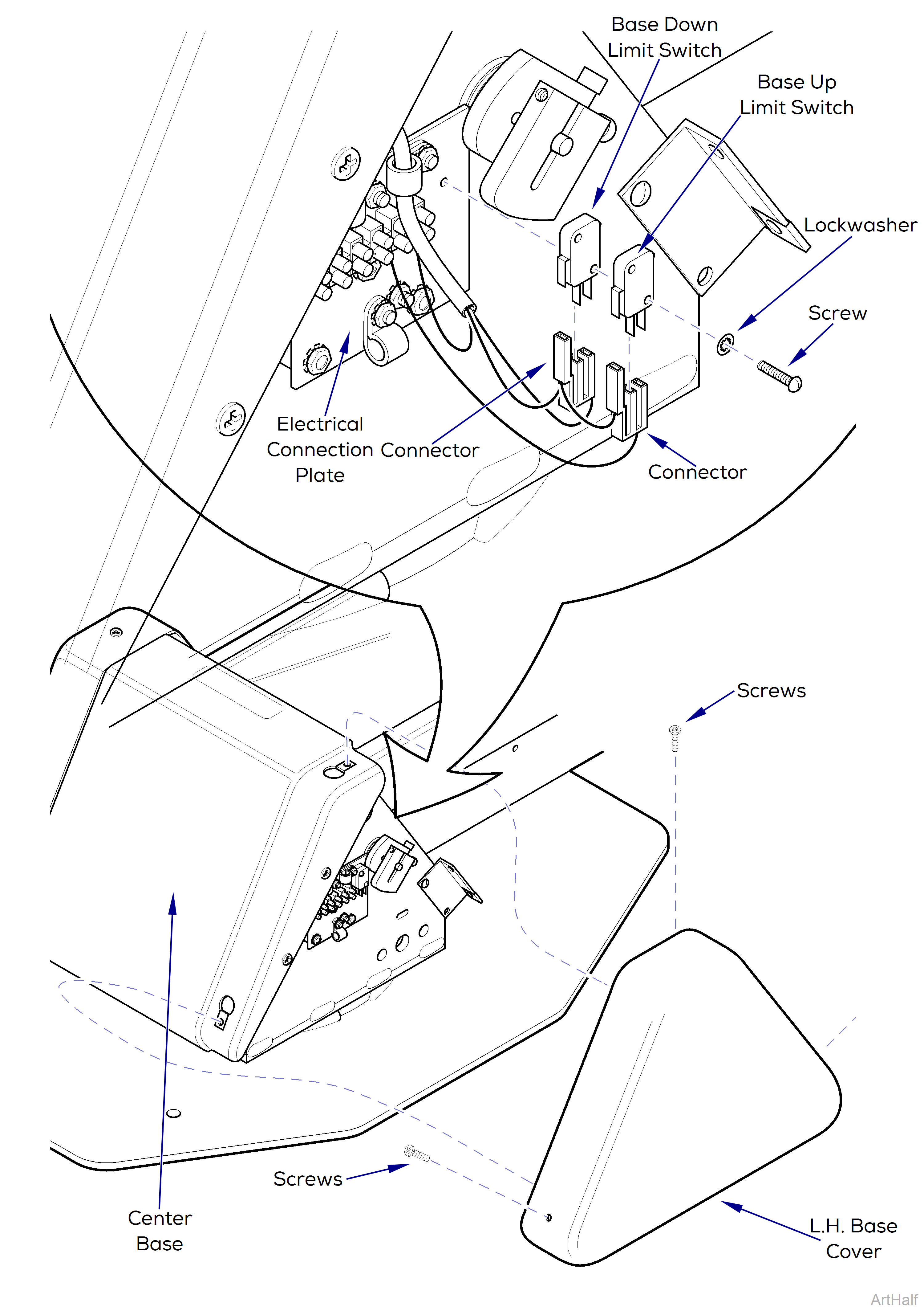
1.Unplug chair power cord.
2.Remove three screws and L.H. base cover from center base cover.
3.Tag and disconnect connector from base up limit switch.
4.Tag and disconnect connector from base down limit switch.
5.Remove two screws, lockwashers, base up, and base down limit switch.
Installation
1.Install base down limit switch and base up limit switch on electrical connection plate and secure with two lockwashers and screws.
2.Connect connector to base down limit switch.
3.Connect connector to base up limit switch.
Adjustment
1.Remove right-hand base cover, three screws.
2.Remove L.H. Center and R.H. platform covers, 4 screws.
3.Pull outward on one corner of bottom lift arm cover until it clears standoff. Repeat step for other corner and remove cover.
Limit switch cam adjustments must be done with table plugged in. Line voltage is present on terminal board near limit switches. Use care not to touch bare wires or terminals. Failure to comply could result in personal injury.
4.Base Up Limit Switch Adjustment
a.Loosen screw and rotate cam up off trip button of Base Up limit switch.
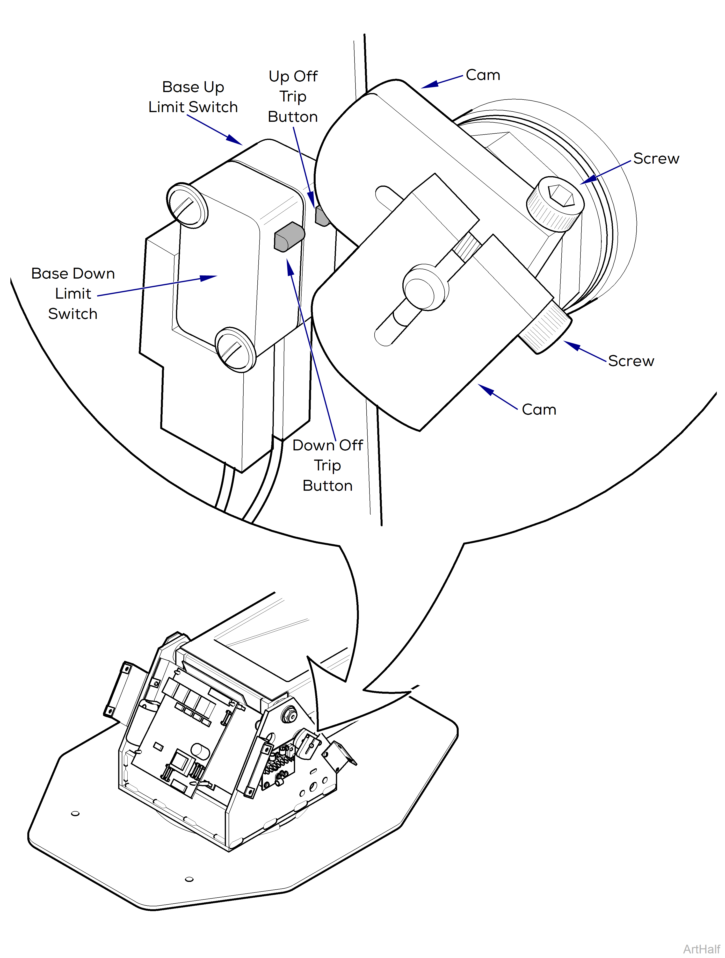
When base motor reaches its limit, release Base Up control button quickly; motor is binding at this point and damage to motor could occur.
b.Raise Base Up function all the way up until motor stops.
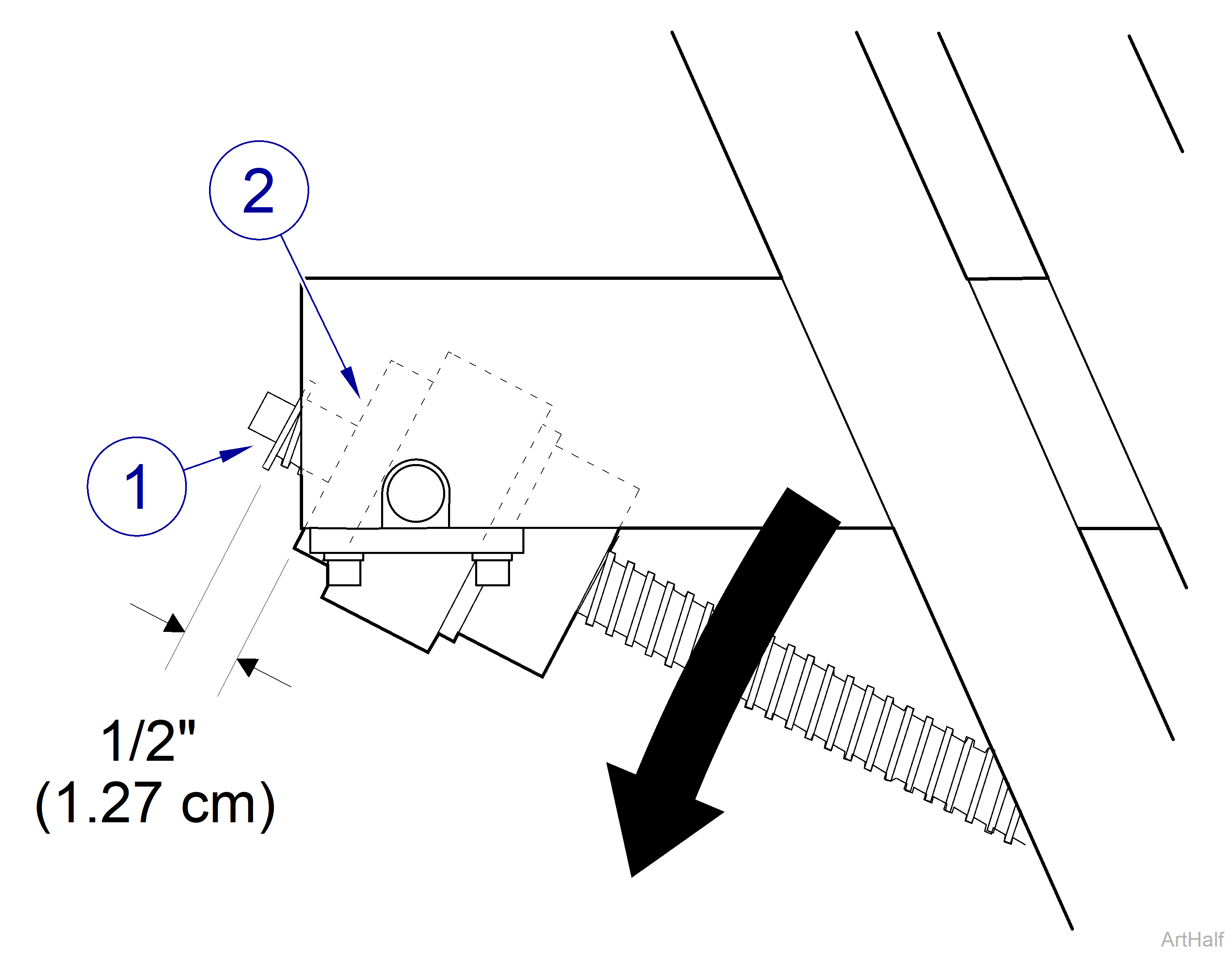
c.Lower Base Down function until flat washer is 1/2” (1.27 cm) from face of trunnion nut.
Rotate Base Up limit switch cam above switch trip button and then downward to trip button during adjustment due to rotational direction of cam.
d.Rotating in downward direction, adjust cam so that it “just” operates trip button of Base Up limit switch; then tighten screw on cam.
5.Base Down Limit Switch Adjustment
a.Loosen screw and rotate cam down off trip button of Base Down limit switch.
Do not run Base Down function any lower than specified in step 7. Doing so could allow chair to physically collide with itself, damaging motor, covers, or other components.
6.Lower Base Down function until measurement between surface of baseplate and top of cross weldment is no lower than 8 5/8 in. ( 21.9 cm) or higher than 8 3/4 in. (22.2 cm).
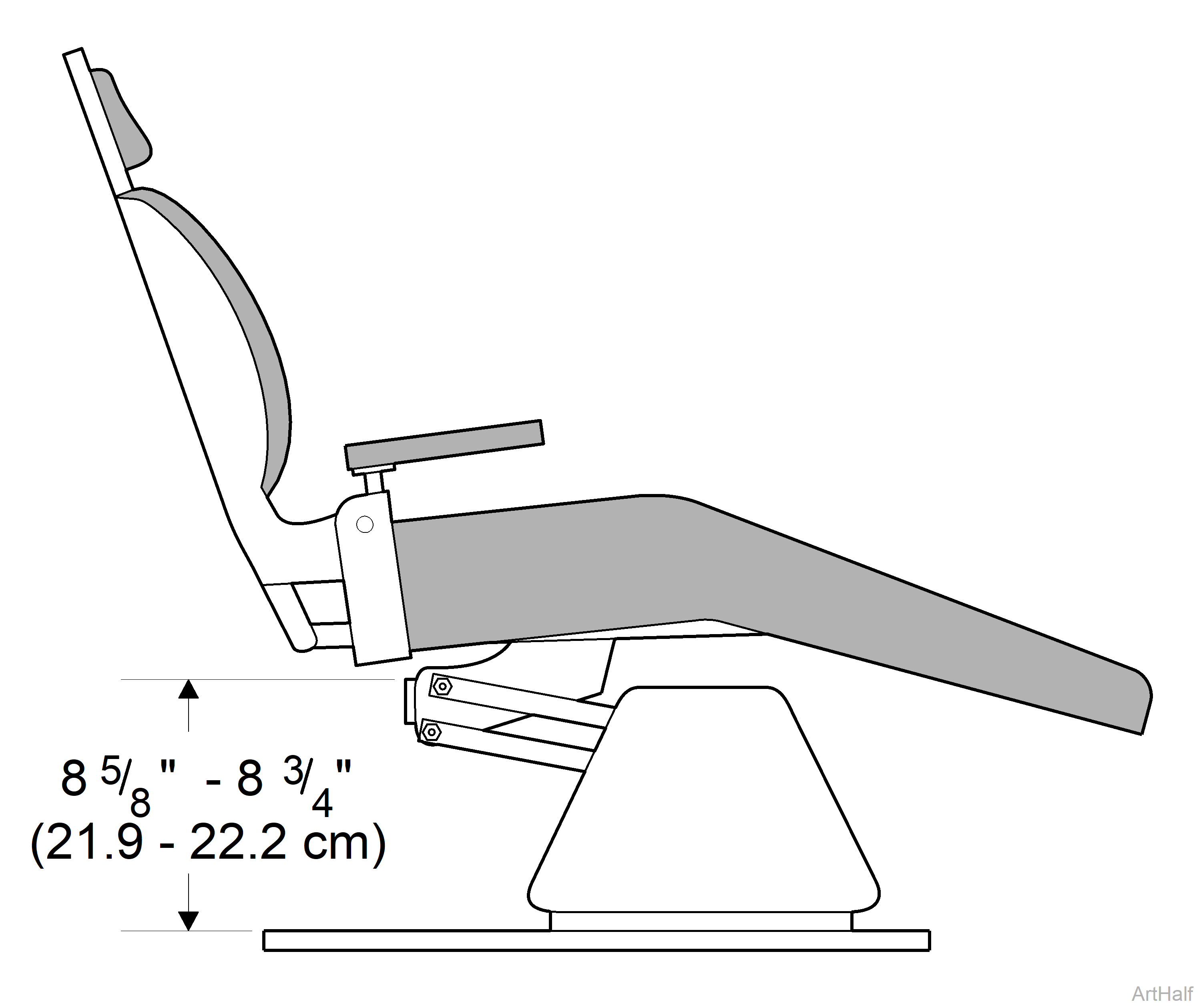
Rotate Base Down limit switch cam below switch trip button and then upward to trip button during adjustment due to rotational direction of cam.
7.Rotating in upward direction, adjust cam so that it “just” operates trip button of Base Down limit switch; then tighten screw on cam.
8.Plug chair power cord into wall outlet and check operation.
9.Install bottom lift arm cover, L.H. and R.H. and center platform covers, four screws.
10.Install R.H. base cover, three screws.
Removal
1.Remove R.H. base cover three screws.
2.Disconnect wire harness.
3.Remove base up program limit switch, two screws.
Installation
1.Install base up program limit switch, two screws.
2.Connect wire harness.
3.Install R.H. base cover, three screws and check operation.
Removal
1.Remove seat upholstery.
2.Raise Base Up all way up and lower Back Down function all way down.
3.Unplug chair power cord.
4.Disconnect switch harness from back up limit switch.
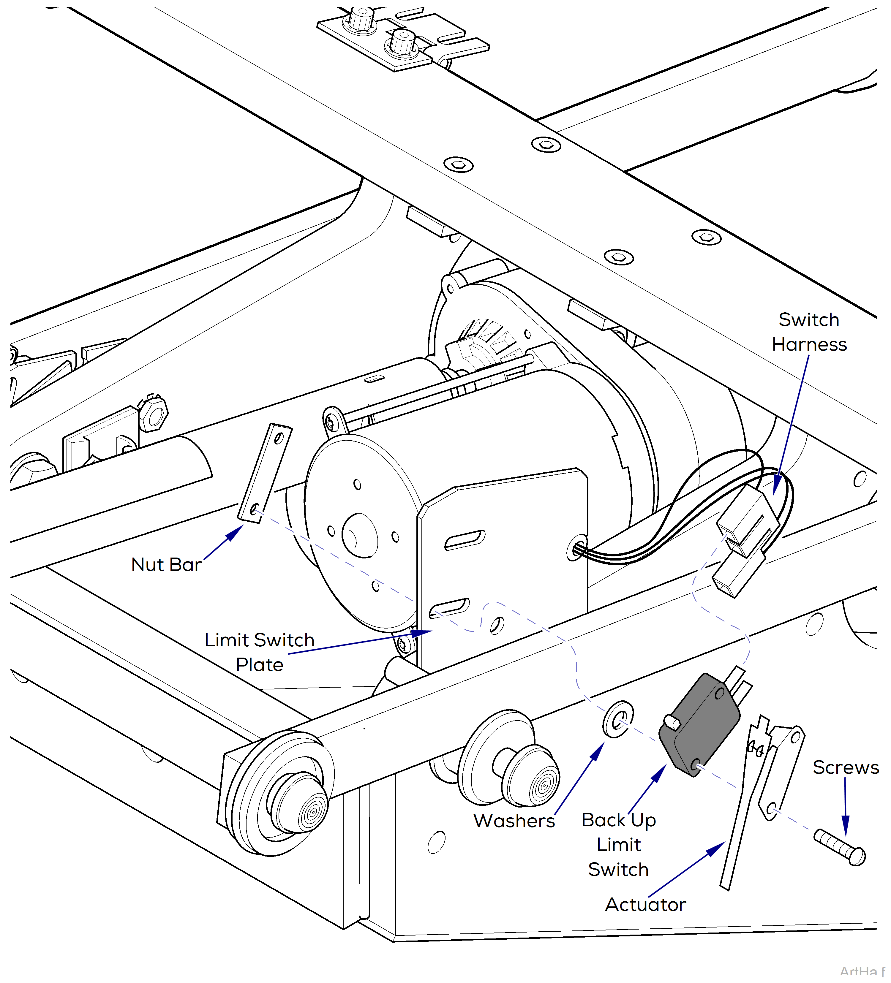
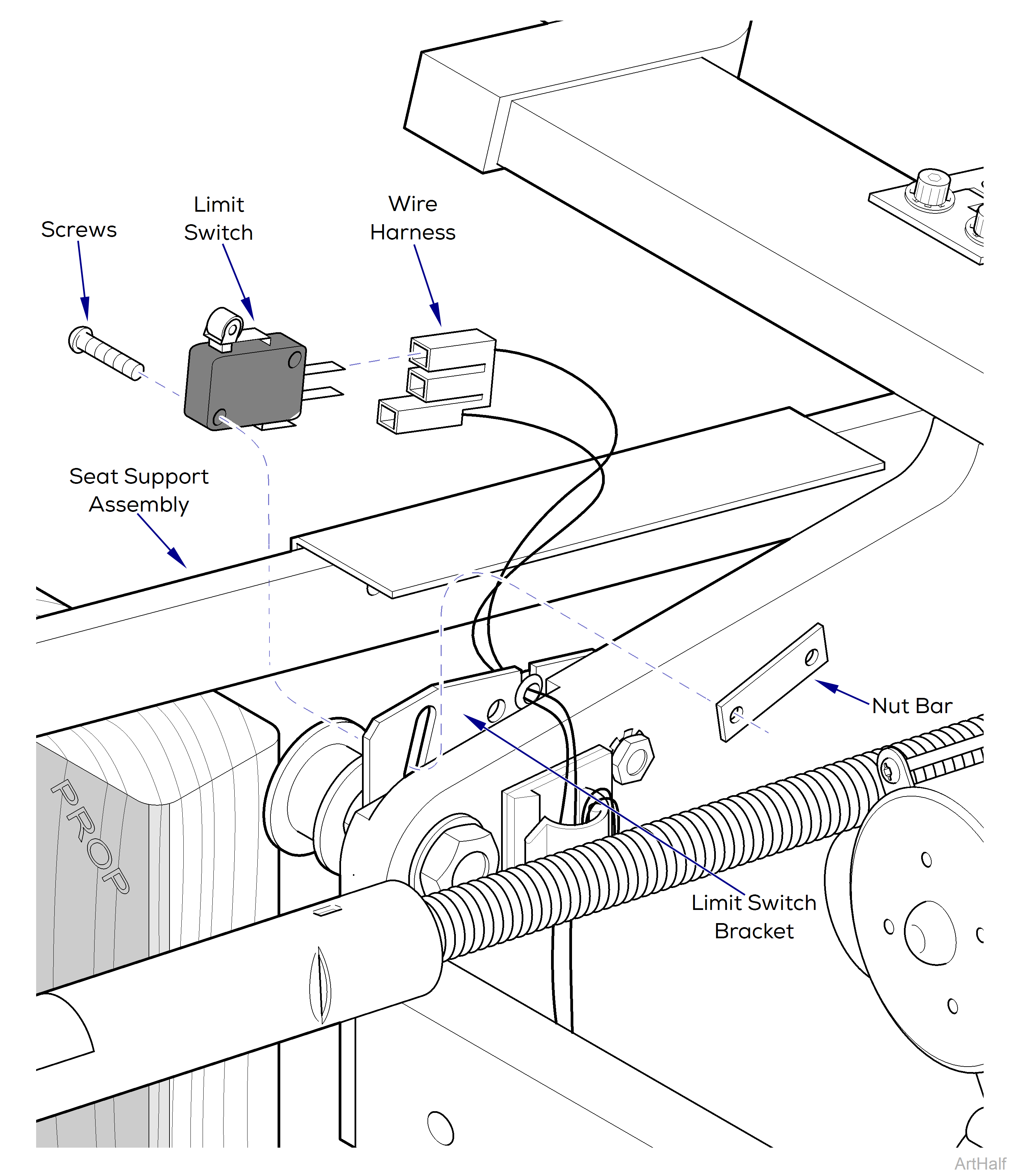
5.Remove two screws, nut bar, back up limit switch, washers, and actuator from limit switch plate.
Installation
1.Assemble two screws, actuator, and two washers on Back Up limit switch.
2.Install back up limit switch assembly on limit switch plate positioning it as far toward foot end as possible and secure with nut bar.
3.Connect switch harness to back up limit switch.
Adjustment
Be sure that Back Up Limit Switch trips to the “open” position before internal limit switch in Back Motor trips.
1.Raise Back Up function all way up until Back Up limit switch is tripped.
If necessary, disconnect switch harness and use an ohmmeter to determine if normally closed (C / NC) contacts have opened and reinstall switch harness.
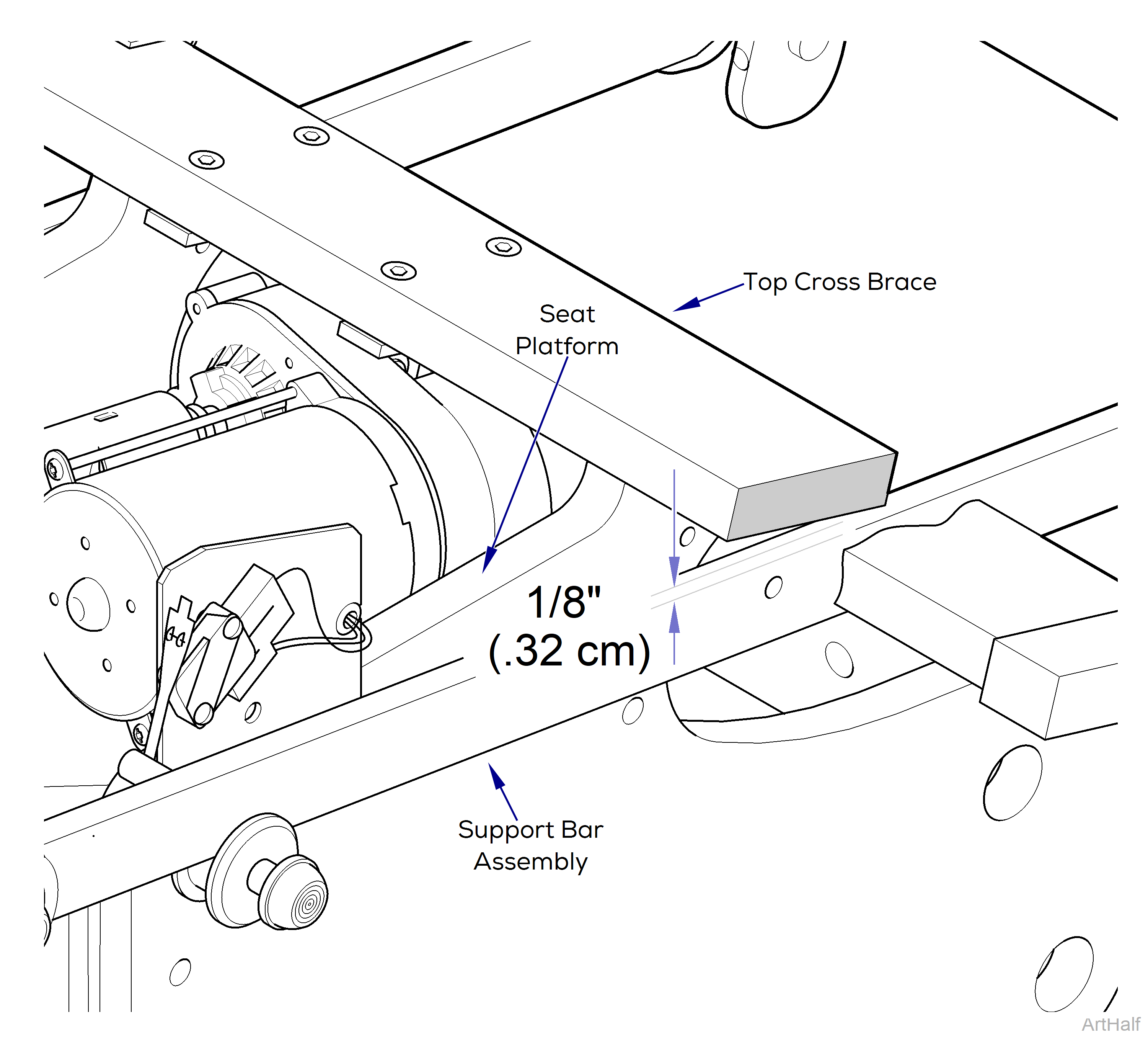
Seat support bar assembly and top cross brace of seat platform should not come in contact when back is all the way up.
2.Distance between seat support bar assembly and top cross brace of seat platform should be approximately 1/8” (0.32 cm).
3.If necessary, loosen two screws and adjust back up limit switch to trip earlier or later.
Removal
1.Raise Base Up all way up and lower Back Down function all way down.
2.Unplug chair from wall outlet.
3.Remove seat upholstery.
4.Lift upward on seat support assembly and place a support beneath it to hold it in place while working on Back Down Program Limit Switch.
5.Disconnect wire harness from back down program limit switch.
6.Remove two screws, limit switch, and nut bar from limit switch bracket.
Installation
1.Install limit switch on limit switch bracket and secure with two screws and nut bar.
2.Connect wire harness.
Adjustment
Assure trip arm does not bottom out on back down program limit switch body when it comes in contact with back down programming plate.
1.Run Auto Operate function and observe. If trip arm bottoms out or does not trip when it comes into contact with programming plate, back down program limit switch needs adjusted.
2.Loosen two mounting screws and adjust back down program limit switch up or down as necessary. Tighten two mounting screws.
3.Check operation.
Removal
1.Raise chair BASE UP function all way up.
2.Unplug chair power cord from wall outlet.
3.Remove R.H. and L.H. base covers, three screws each.
4.Remove center base cover, four screws.
5.Remove L.H. Center and R.H. platform covers, 4 screws.
6.Pull outward on one corner of bottom lift arm cover until it clears standoff. Repeat step for other corner and remove cover.
7.Disconnect wire harness from malfunctioning Safety Bail limit switch.
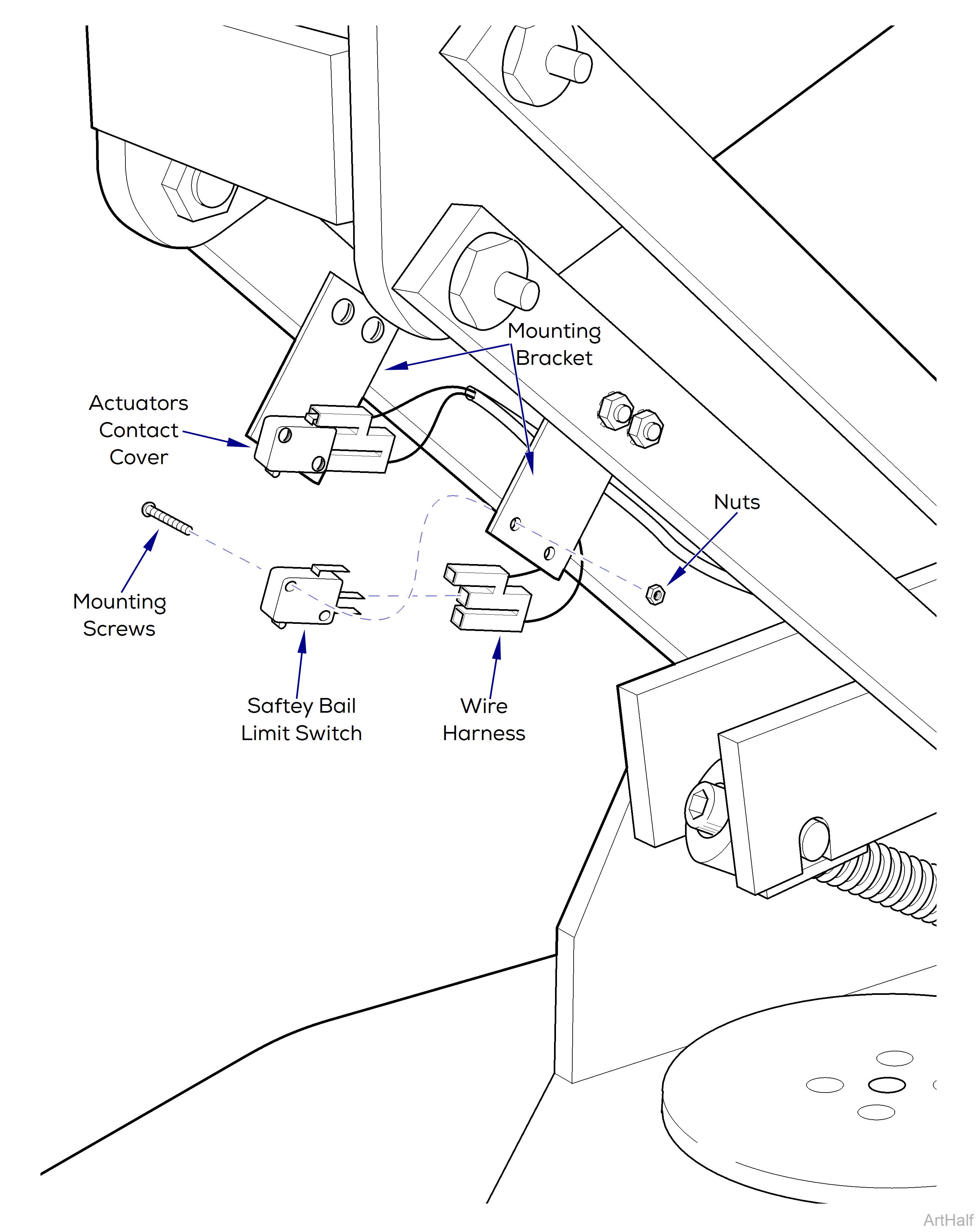
8.Remove two mounting screws and nuts and remove limit switch.
Installation
1.Place limit switch in position on mounting bracket and secure with two mounting screws and nuts.
2.Attach wire harness.
Actuator on Safety Bail Limit Switches are operated when inside surface of bottom lift arm cover comes in contact with them. Position switch mounting brackets so actuators contact cover. Failure to comply could result in switches not operating and personal injury.
3.Loosen two mounting screws for limit switch bracket, then push bottom of bracket toward foot end of chair as far as possible and re-tighten screws.
4.Install bottom lift arm cover, center, R.H. and L.H. platform covers, four screws.
5.Install center base cover, four screws
6.Install R.H. and L.H. base covers, six screws.
7.Plug in chair and check operation. Press upward on the center platform cover as chair is descending. Chair should stop descending.
Removal
1.Unplug chair power cord.
2.Remove back upholstery.
3.Disconnect wire harness from membrane switch panel.
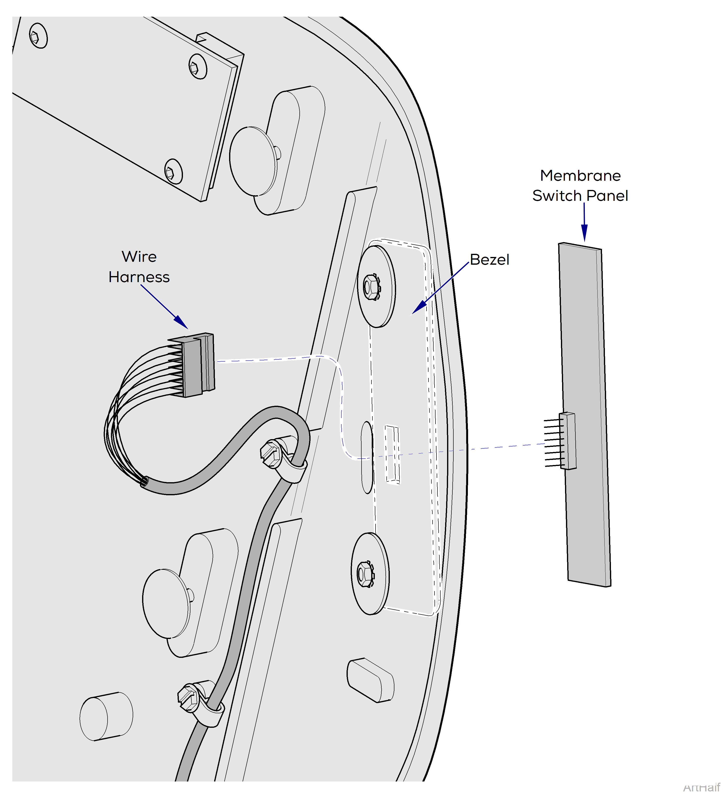
4.Peel membrane switch off bezel.
Installation
1.After removing protective backing from membrane switch, place switch in position on bezel and press firmly to adhere switch to bezel.
2.Connect wire harness to membrane switch panel.
3.Install back upholstery.
4.Plug chair power cord into outlet and check operation.
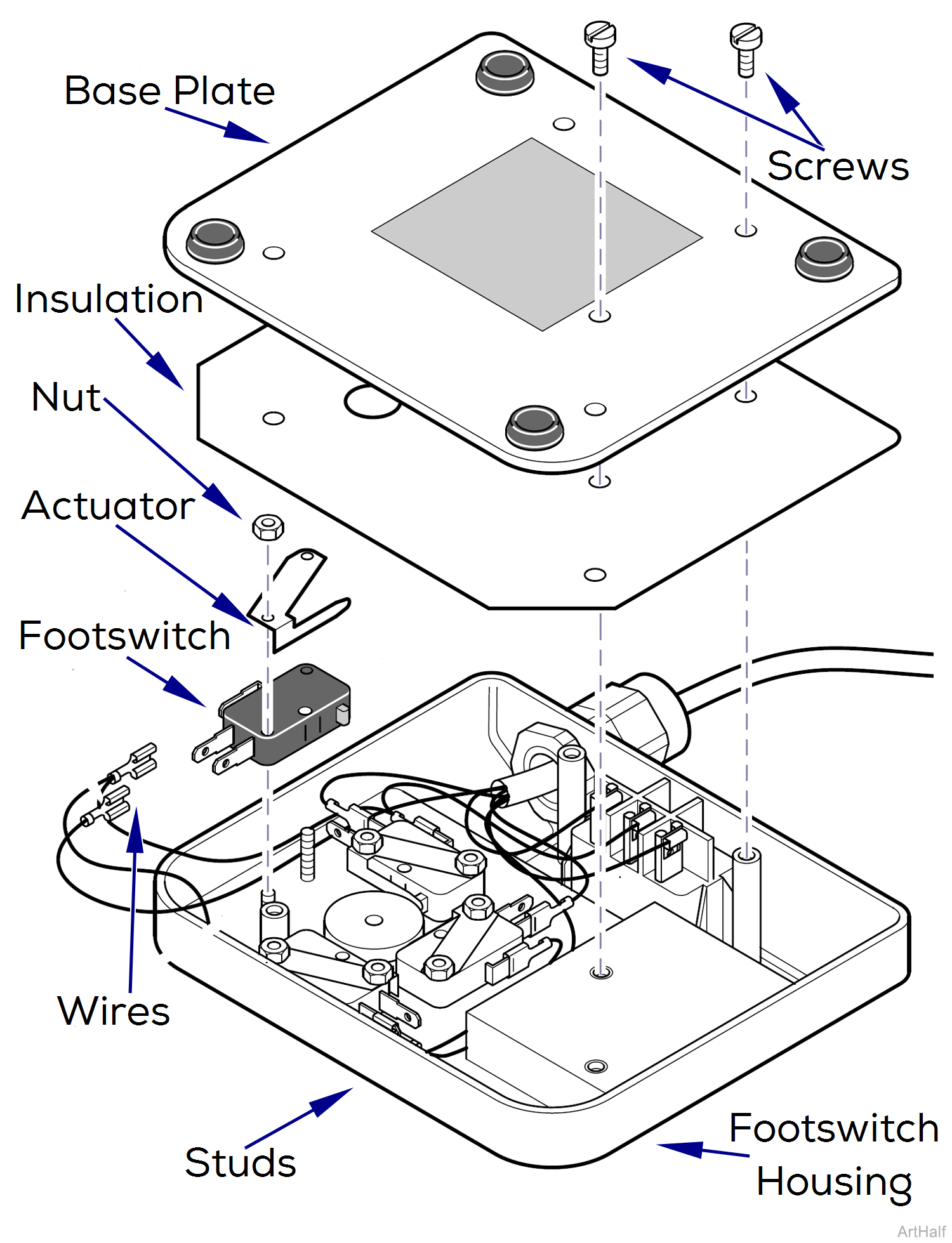
Removal
1.Unplug chair power cord.
2.Remove five screws, base plate, and insulation from footswitch housing.
3.Remove two nuts and actuator from two studs.
4.Remove footswitch; then tag and disconnect wires from footswitch.
Installation
1.Connect wires to terminals of footswitch.
2.Install footswitch and actuator on studs and secure with two nuts.
3.Install insulation and base plate on footswitch housing and secure with five screws.
4.Plug in chair power cord.
Removal
1.Unplug chair power cord.
2.Remove five screws, base plate, and insulation from footswitch housing.
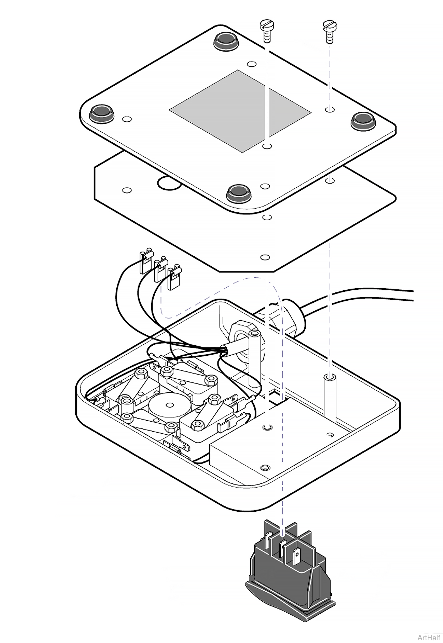
3.Tag and disconnect wires footswitch.
4.While simultaneously pushing in on four locking tabs of footswitch, push footswitch out of footswitch housing.
Installation
Make sure footswitch is installed in same orientation as shown in illustration. Failure to do so will result in incorrect actions when the Auto Operate (Green) or Auto Exit (Yellow) functions are selected.
1.Push footswitch into footswitch housing until it snaps into place and is fully seated.
2.Connect wires to terminals of footswitch.
3.Install insulation and base plate on footswitch housing and secure with five screws.
4.Plug in chair power cord.
Removal
1.Raise Base Up function all way up.
2.Unplug chair power cord.
3.Remove R.H. base cover, three screws.
4.Place Brake lever in Unlocked position.
5.Remove disc lock, four screws.
6.Remove brake block assembly.
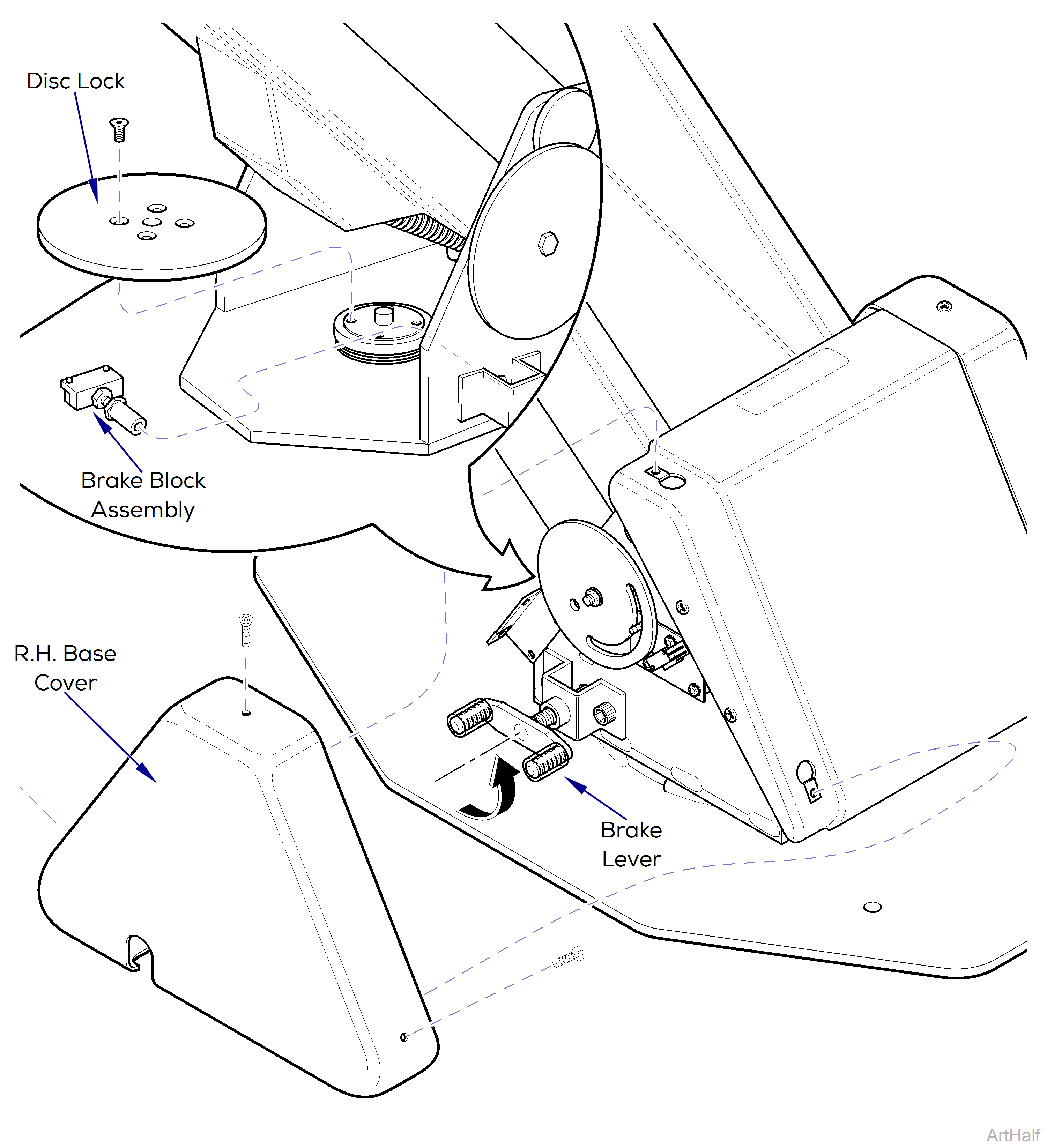
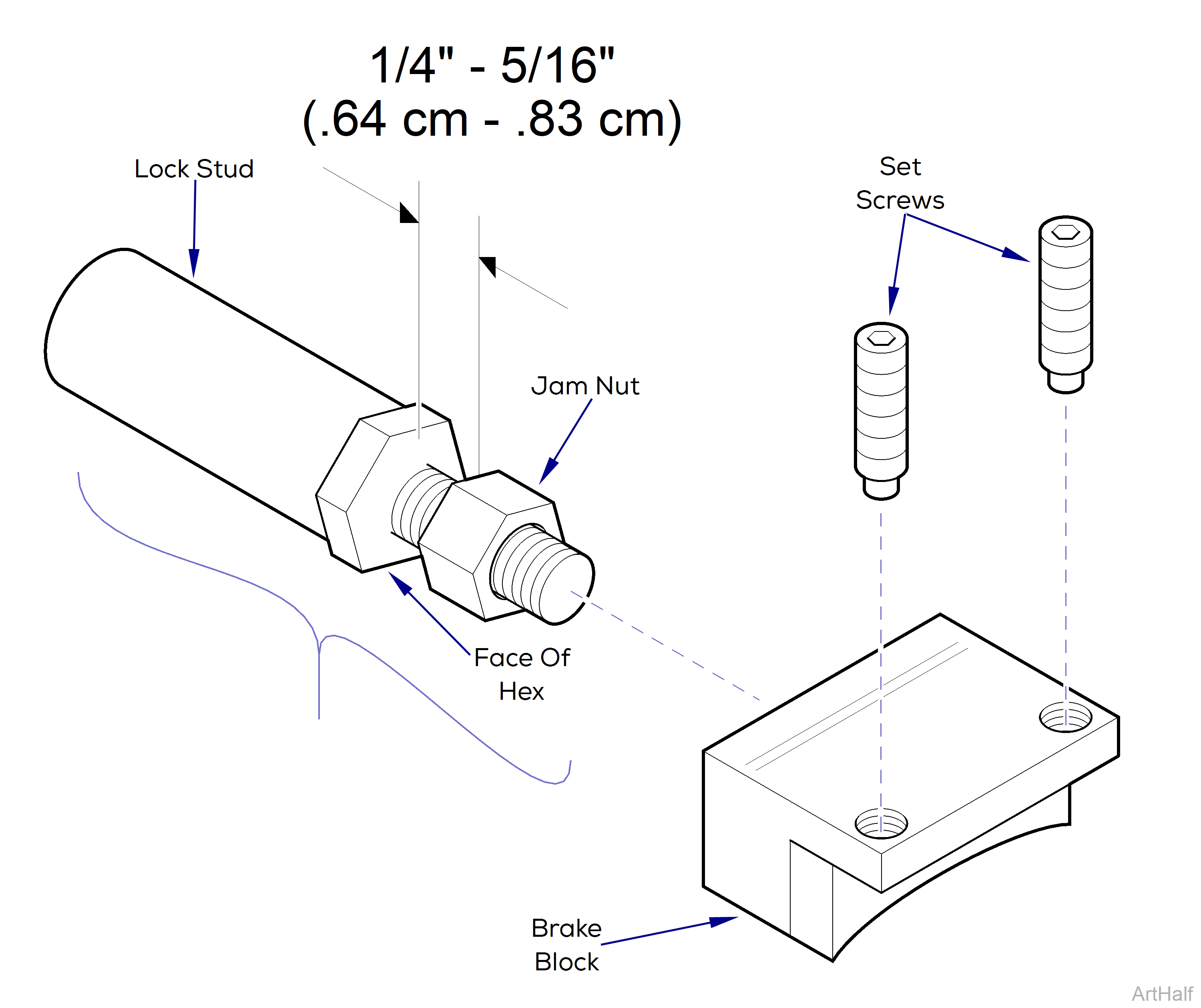
7.Unscrew brake block from lock stud.
8.Remove two set screws from brake block.
Installation
Inspect nylon tipped set screws. If worn or damaged replace screws.
1.Install two set screws in brake block.
When assembling brake block, position jam nut on lock stud so there is approximately 1/4" to 5/16" distance between jam nut and face of hex on lock stud.
2.Assemble brake block and lock stud.
3.Insert brake block assembly into hole of upright housing assembly.
4.Install disc lock and secure with four screws.
Adjustment
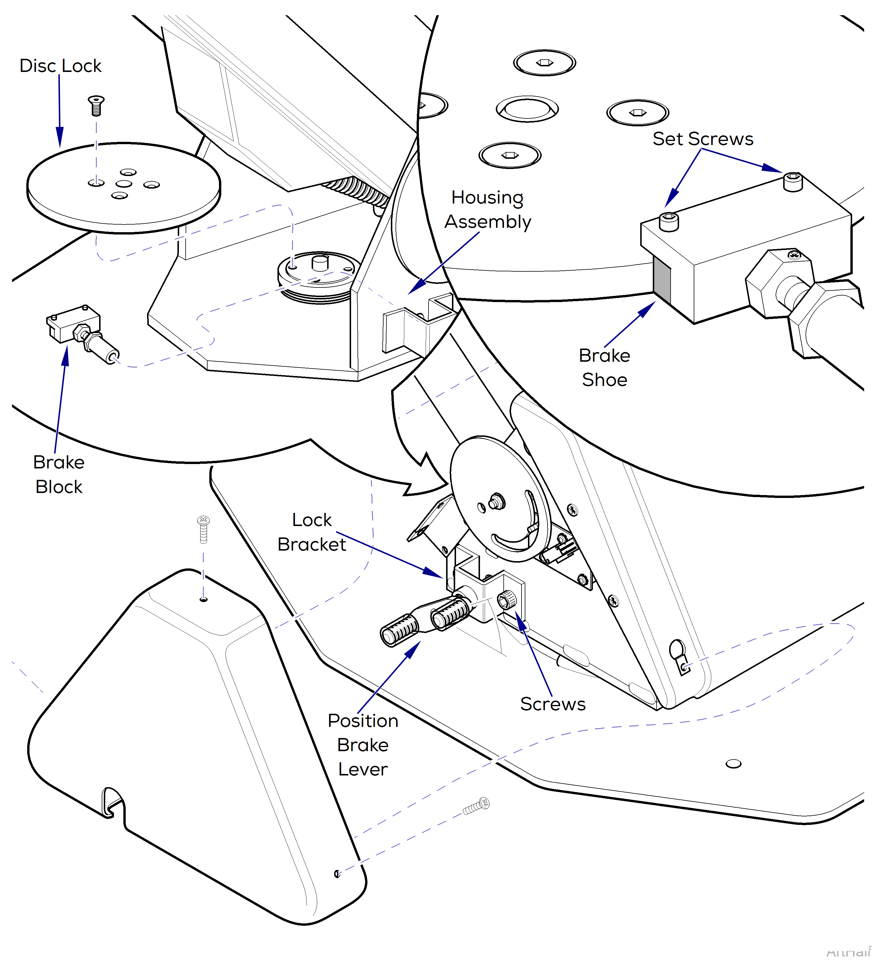
1.Loosen two screws that secure rotational lock bracket to upright housing assembly.
2.Position brake lever so that it is at a 45° angle as shown in illustration.
Make sure brake shoe is seated correctly against disc lock. Nylon tipped set screws must be adjusted to hold brake block in a level position to prevent uneven wear on brake shoe. For adjustment to work correctly, brake lever must continue to be pushed on firmly while screws are being tightened.
3.While pulling upward on brake lever, push inward to force brake shoe and set screws firmly against brake disc; then tighten screws.
4.Position brake lever in Brake position and check adjustments.
5.Install R.H. base cover.
Adjustment
1.Raise Back Up function all the way up.
2.Remove back upholstery.
3.Loosen two jam nuts.
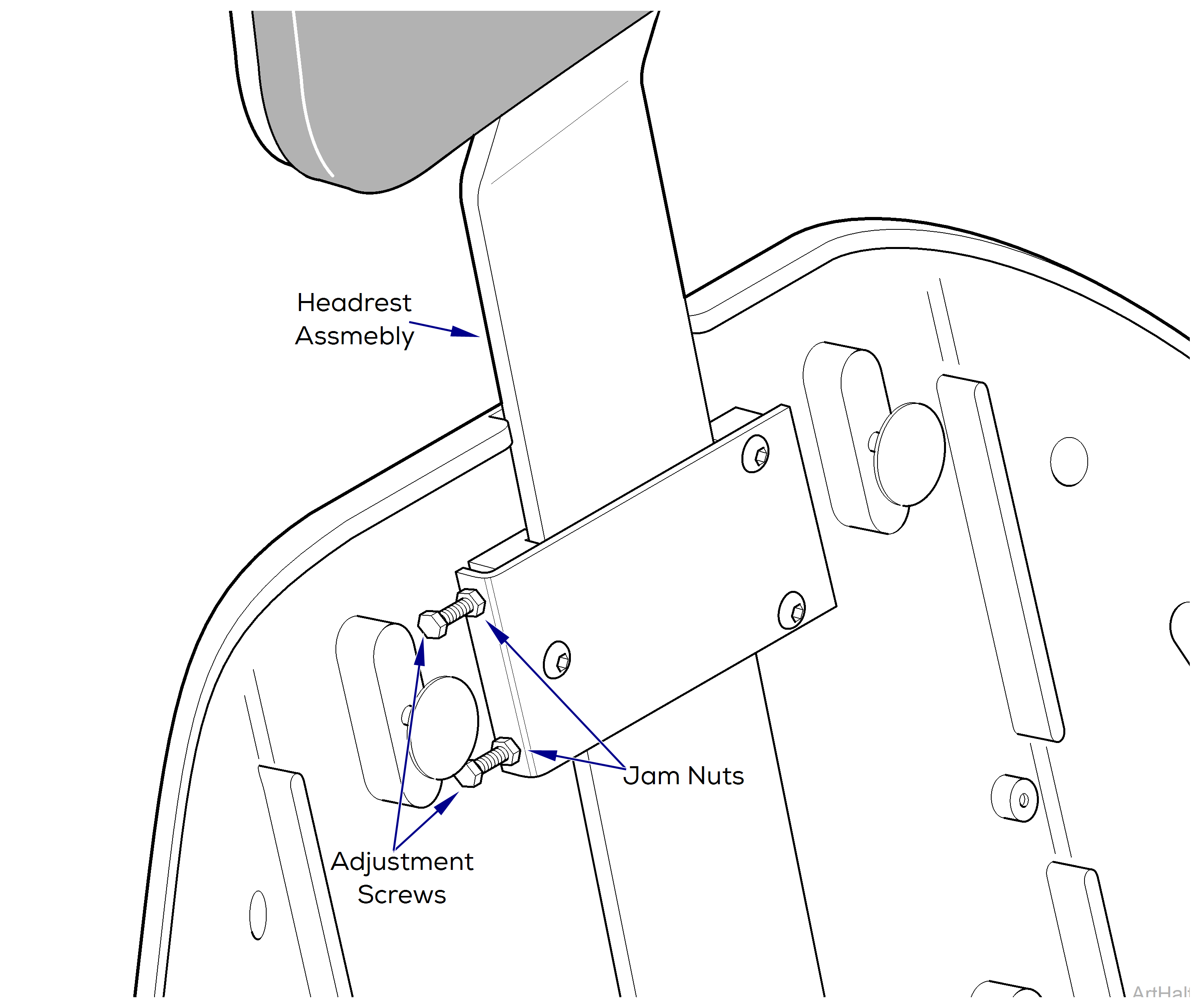
Tighten or loosen two adjustment screws evenly to allow for full and even surface contact of friction tangs. Failure to do so could result in uneven friction braking.
4.If headrest assembly slides down by itself or moves too easily, tighten two adjustment screws.
If headrest assembly requires excessive force to position, loosen two adjustment screws.
5.Test friction setting by sliding headrest assembly in and out. Repeat step until desired friction setting is achieved.
6.While holding adjustment screws with a wrench, tighten jam nuts.
7.Install back upholstery.
