Biltmore/Knight Chairs Troubleshooting
| Problem | Symptom | Probable Cause | Check | Correction |
|---|---|---|---|---|
| Chair will not operate when any function is selected (from any of the membrane switch panels or foot control switches). | When a membrane switch panel or foot control switch is pressed, nothing happens and relays cannot be heard energizing. | Power cord is not plugged into facility wall outlet. | Check to see if power cord is plugged in. | Plug power cord into facility wall outlet. |
| Facility circuit breaker providing power to chair is tripped. | Check to see if facility circuit breaker is tripped. One way of checking this is to plug a lamp into wall outlet that chair was plugged into. | If facility circuit breaker is tripped, determine what caused circuit breaker to trip, correct problem, and then reset / replace circuit breaker. | ||
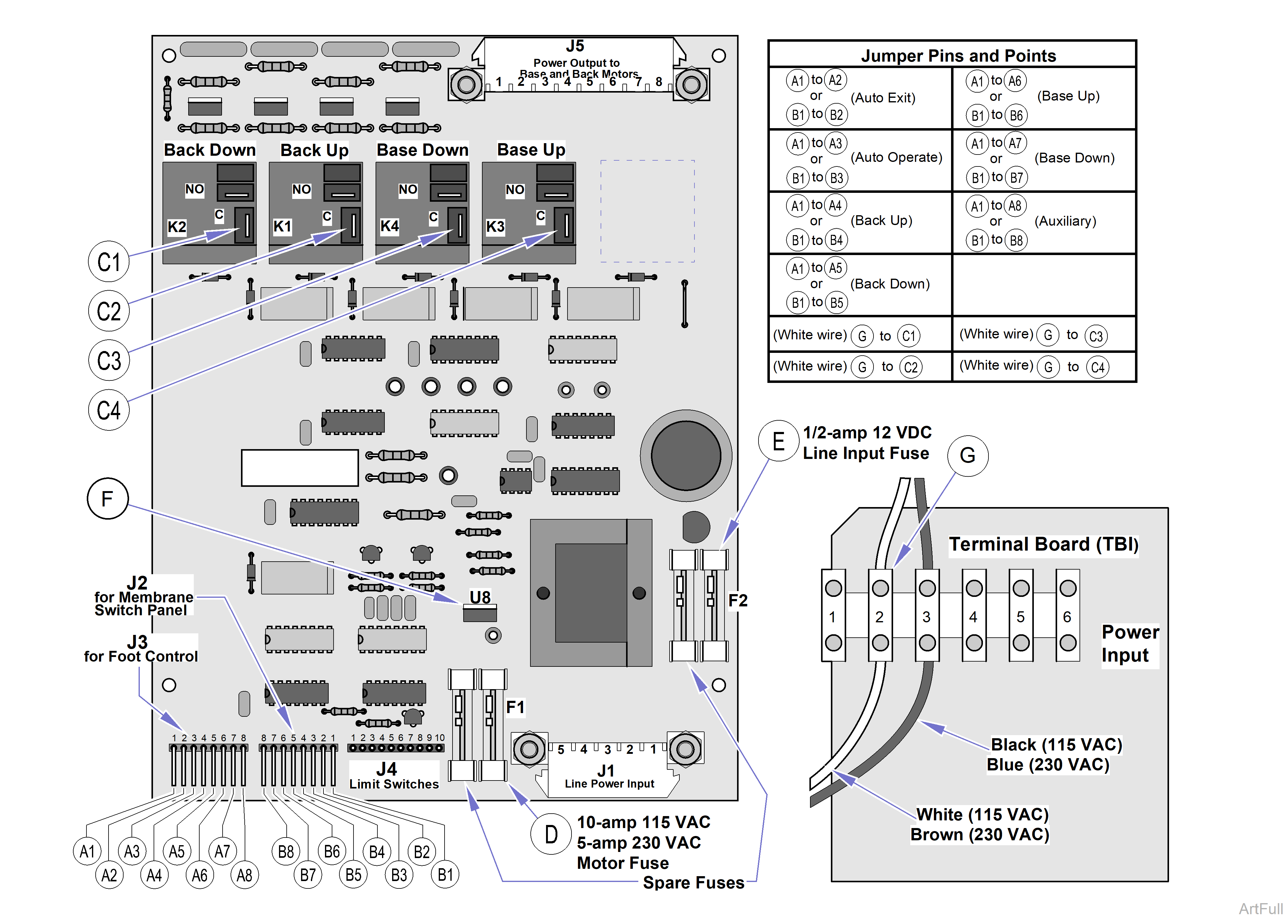
| Wire connections are loose. | Check all wiring connections from power cord to terminal board to PC circuit board. Use a multimeter to perform a continuity check on wires. Check for line voltage at plug J1 (line power input) on pins 1 (white or brown) and 4 (black or blue). | Clean any dirty connections. Tighten any loose connections. Replace any damaged connections. Refer to: Troubleshooting 115 or 230 VAC System PC Board and Terminal Board. | ||
| 1/2 amp, 12 VDC, line input fuse is blown. | Refer to: Troubleshooting 115 or 230 VAC System P.C. Board and Terminal Board for location of 12 VDC line input fuse. Perform continuity check on fuse. | Replace blown line input fuse. There is a spare fuse located directly to the left of the fuse. | ||
| PC circuit board is malfunctioning. | Check for line voltage by placing one meter probe on TB1, terminal 2 and the other on J5 (Power Output to Motors), pin 2 (white) and then on pin 5 (blue). | If no voltage replace Printed Circuit (PC) Board. | ||
| No actions can be initiated from membrane switch panel and foot control. | Chair has power, but no functions can be initiated from membrane switch panel and foot control. | Line Motor circuit fuse is blown. 115 VAC fuse, 10 Amp 230 VAC fuse, 5 Amp | Refer to: Troubleshooting 115 or 230 VAC System P.C. Board and Terminal Board for location of motor circuit fuse. Perform continuity check on fuse. | Replace blown motor circuit fuse. There is a spare fuse located directly to the left of the line input fuse which may be used. |
| PC circuit board is malfunctioning. | Check all wiring connections from power cord to terminal board to PC circuit board. Use a multimeter to perform a continuity check on wires. Check for line voltage at plug J1 (line power input) on pins 1 (white or brown) and 4 (black or blue). Refer to: Troubleshooting 115 or 230 VAC System P.C. Board and Terminal Board. | Replace wire harness or Printed Circuit (PC) Board, whichever is defective. | ||
| One or more functions cannot be initiated from membrane switch panels. | Some functions can be initiated with hand control, but at least one cannot. | Membrane switch panel is malfunctioning (a switch membrane is malfunctioning). | Refer to: Troubleshooting 115 or 230 VAC System P.C. Board and Terminal Board. Use a jumper wire to jump the 12 VDC pins of connector J2: B1 & B2 (Auto Exit), B1 & B3 (Auto Operate), B1 & B4 (Back Up), B1 & B5 (Back Down), B1 & B6 (Base Up), B1 & B7 (Base Down), B1 & B8 (Auxiliary), Each function should operate when jumped. | If all functions operate correctly when jumped, then fault is in the membrane switch panel. If so, replace membrane switch panel. Refer to:Membrane Switch Panel (Biltmore Classic only) If a function still does not work even when jumpered, fault is in motor circuit or PC circuit board. Continue troubleshooting using this guide. |
| Wire connections loose. | Check all wiring connections between membrane switch panel and PC circuit board. | Clean any dirty connections. Tighten or repair any loose or damaged connections. | ||
| PC circuit board is malfunctioning. | Replace suspect PC circuit board with known working PC circuit board. | Replace Printed Circuit (PC) Board. | ||
| One or more functions cannot be initiated from foot control. | Some functions can be initiated with foot control, but at least one cannot. | Foot control is malfunctioning a foot control switch is malfunctioning. | Perform a continuity check on each N.O. foot control switch in foot control (when switch is pressed, switch circuit should be closed) See Wiring Diagrams. | If foot control switch does not pass continuity check, replace Manual Footswitch. |
| Refer to: Troubleshooting 115 or 230 VAC System PC Board and Terminal Board. Use a jumper wire to jump the 12 VDC pins of connector J3: A1 & A2 (Auto Exit), A1 & A3 (Auto Operate), A1 & A4 (Back Up), A1 & A5 (Back Down), A1 & A6 (Base Up), A1 & A7 (Base Down), Each function should operate when jumped. | If all functions operate correctly when jumped, then fault is in foot control switch of nonoperating function. If so, replace the malfunctioning switch of the foot control. Refer to: Manual Footswitch or Auto/Exit Operate Footswitch. If a function still does not work even when jumpered, fault is in motor circuit or PC circuit board. Continue troubleshooting using this guide. | |||
| Wire connections loose. | Check all wiring connections between foot control switches and PC circuit board. | Clean any dirty connections. Tighten or repair any loose or damaged connections. | ||
| BACK UP and BACK DOWN functions do not work. All other functions work. | When BACK UP and BACK DOWN buttons are pressed, chair will not move (all other functions work). | PC circuit board is malfunctioning. | Replace suspect PC circuit board with known working PC circuit board. | Replace PC board. |
| Thermal overload switch in back motor is activated to the open position. | Check for continuity between White and Red, and White and Blk Motor leads. Internal limit switches must be closed. Refer to: Wiring Diagrams. | Wait 10 to 20 minutes to allow back motor to cool and bimetal thermal protector to reset. (Motor is for intermittent use and should not be run constantly). | ||
| Back capacitor is weak or blown. | Replace suspect back capacitor with known working back capacitor. | Replace Back Motor Capacitor. | ||
| Wiring connections loose. | Check all wiring connections to back motor. | Clean any dirty connections. Tighten any loose connections. Replace any damaged connections. | ||
| BACK UP and BACK DOWN functions do not work. All other functions work (continued) | When BACK UP and BACK DOWN buttons are pressed, chair will not move (all other functions work) (continued) | Back motor is malfunctioning. | Replace suspect back motor with known working back motor assembly. | Replace Back Motor. |
| BACK UP function works, but BACK DOWN function does not or BACK DOWN function works, but BACK UP function does not. All other functions work. | Back motor runs in one direction, but not the other. | Wiring connections loose. | Check all wiring connections from PC circuit board to back motor assembly. | Clean any dirty connections. Tighten any loose connections. Replace any damaged connections. |
| Membrane switch panel is malfunctioning (BACK UP or BACK DOWN switch membrane is malfunctioning). | Refer to: Wiring Diagams. Use a jumper wire to jump 12 VDC pins of connector J2: B1 & B4 (Back Up), B1 & B5 (Back Down), Each function should operate when jumped. | If both functions operate correctly when jumped, then fault is in the membrane switch panel. If so, replace membrane switch panel. Refer to:Membrane Switch Panel If a function still does not work even when jumpered, fault is in motor circuit or PC circuit board. | ||
| Back Up Limit Switch is malfunctioning or is out of adjustment. | Perform continuity check on N.C. Back Up Limit Switch and check limit switch adjustment. | Replace Normally Closed, Back Up Limit Switch. Refer to: Back Up Limit Switch | ||
| Back motor is malfunctioning. | Replace suspect back motor with known working back motor. | Replace back motor. | ||
| Back Down or Back Up motor internal limit switch is malfunctioning or out of adjustment. | Perform continuity check on motor internal limit switches. | Replace Back Motor. | ||
| Relay (K1 or K2) for Up or Down function on PC circuit board is malfunctioning). | Refer to: Wiring Diagams for this check. Use a jumper wire to jump line voltage Test Points C2 and G; Back Up function should run. Use a jumper wire to jump line voltage Test Points C1 and G; Back Down function should run. If motor runs when a relay is jumped, fault is in membrane switch panel, wiring, or PC circuit board. If motor does not run when a relay is jumped, fault is in wiring or back motor. | Replace PC Circuit Board. | ||
| BASE UP and BASE DOWN functions do not work. All other functions work. | When BASE UP and BASE DOWN buttons are pressed, chair will not move (all other functions work). | Thermal overload switch in base motor is activated to the open position. | Check for continuity between Blue (common) and White (115 VAC) or Brown (230 VAC), and Blue (common) and Black Motor leads. | Wait 10 to 20 minutes to allow back motor to cool and bimetal thermal protector to reset. (Motor is for intermittent use and should not be run constantly). |
| Base capacitor is weak or blown. | Replace suspect base capacitor with known working capacitor. | Replace Base Capacitor. | ||
| BASE UP and BASE DOWN functions do not work. All other functions work (continued). | When BASE UP and BASE DOWN buttons are pressed, chair will not move (all other functions work) (continued). | Wiring connections loose. | Check all wiring connections to base motor assembly. | Clean any dirty connections. Tighten any loose connections. Replace any damaged connections. |
| Base motor assembly is malfunctioning. | Replace suspect base motor assembly with known working base motor assembly. | Replace Base Motor. | ||
| BASE UP function works, but BASE DOWN function does not or BASE DOWN function works, but BASE UP function does not. All other functions work. | Base motor runs, but its shaft does not turn. | Base motor worm wheel is broken. | Check worm wheel in base motor. | Replace base motor worm gear. |
| Base motor runs in one direction, but not the other. | Wiring connections loose. | Check all wiring connections from PC circuit board back motor assembly. | Clean any dirty connections. Tighten any loose connections. Replace any damaged connections. | |
| Membrane switch panel is malfunctioning (BASE UP or BASE DOWN switch membrane is malfunctioning). | Refer to: Wiring Diagrams. Use a jumper wire to jump the 12 VDC pins of connector J2: B1 and B6 (Base Up), B1 & B7 (Base Down), Each function should operate when jumped. | If both functions operate correctly when jumped, then fault is in the membrane switch panel. If so, replace membrane switch panel. If a function still does not work even when jumpered, fault is in motor circuit or PC circuit board. | ||
| Base Up Limit Switch is malfunctioning or is out of adjustment. | Perform continuity check on N.C. Base Up Limit Switch and check limit switch adjustment (should be a closed circuit when limit switch is not tripped). | Adjust or replace Normally Closed Base Up Limit Switch. | ||
| Base Down Limit Switch is malfunctioning or is out of adjustment (causing an open circuit). | Perform continuity check on N.C. Base Down Limit Switch and check limit switch adjustment (should be a closed circuit when limit switch is not tripped). | Adjust or replace Normally Closed Base Up Limit Switch. | ||
| One or both of the Safety Bail N/C Limit switches are open. | Perform continuity check on N.C. Safety Bail Limit Switches and check limit switch adjustments (should be a closed circuit when limit switch is not tripped). | Adjust or replace Normally Closed Safety Bail Limit Switch(es). | ||
| Base motor is malfunctioning. | Replace suspect base motor with known working base motor. | Replace base motor. | ||
| BASE UP function works, but BASE DOWN function does not or BASE DOWN function works, but BASE UP function does not. All other functions work (continued). | Base motor runs in one direction, but not the other (continued). | Relay (K4 or K3) for Up or Down function on PC circuit board is malfunctioning. | Refer to: Troubleshooting 115 or 230 VAC System P.C. Board and Terminal Board. Use a jumper wire to jump Line Voltage Test Points C4 and G; Base Up function should run. Use a jumper wire to jump Line Voltage Test Points C3 and G; the Base Down function should run. If the motor runs when a relay is jumped, the fault is in the membrane switch panel, wiring, or PC circuit board. If the motor does not run when a relay is jumped, the fault is in the wiring or base motor. | After checking the wiring, membrane switch assemblies and base motor replace PC circuit board. |
| Auto Operate function does not work properly. | Nothing happens when Auto Operate button is pressed (all other functions work). | Membrane switch panel is malfunctioning (Auto Operate switch membrane is malfunctioning). | Refer to: Troubleshooting 115 or 230 VAC System P.C. Board and Terminal Board. Use a jumper wire to jump 12 VDC pins of connector J2: B1 & B3 (Auto Operate), The Auto Operate function should operate when jumped. | If Auto Operate function operates correctly when jumped, then fault is in the membrane switch panel. If so, replace membrane switch panel. Refer to para 4.15. If a function still does not work even when jumpered, fault is in motor circuit or PC circuit board. |
| Wiring connections loose. | Check all wiring connections to membrane switch panels, Back Down Program limit switch, and Base Up Program limit switch. | Clean any dirty connections. Tighten any loose connections. Replace any damaged connections. | ||
| Back Down Program limit switch is malfunctioning (causing open circuit). | Perform continuity check on N.C. Back Down Program limit switch (should be a closed circuit when limit switch is not tripped). | Replace Back Down Program limit switch. | ||
| Back Down Program limit switch is normally tripped (limit switch is not adjusted to stop back section at operator’s desired position). | Check with operator to see if operator is aware that the back section can be manually adjusted to be stopped where desired in the Auto Operate function. | Show the operator how to manually adjust the Back Down Program limit switch Refer to: Back Programming Procedure in the Installation Manual. | ||
| Back Down Program limit switch trip arm is not contacting back programming plate. | Check to see if Back Down Program limit switch trips when it contacts the back programming plate. | Adjust the Back Down Program limit switch so it trips properly when it contact the back programming plate. | ||
| Base Up Program limit switch is malfunctioning (causing open circuit). | Perform continuity check on N.C Base Up Program limit switch (should be a closed circuit when limit switch is not tripped). | Replace Base Up Program limit switch. | ||
| Auto Operate function does not work properly (continued). | Nothing happens when Auto Operate button is pressed (all other functions work) (continued). | Base Up Program limit switch is normally tripped (limit switch is not adjusted to stop base function at operator’s desired position). | Check with operator to see if operator is aware that the base section can be manually adjusted to stop where desired in the Auto Operate function. |
Show the operator how to manually adjust the Base Up limit switch Refer to: Base Programming Procedure in the Installation Manual. |
| PC circuit board is malfunctioning. | Replace suspect PC circuit board with known working PC circuit board. | Replace PC circuit board. | ||
| Auto Exit function does not work properly. | Nothing happens when Auto Exit button is pressed (all other functions work). | Membrane switch panel is malfunctioning (Auto Exit switch membrane is malfunctioning). | Refer to: Wiring Diagrams. Use a jumper wire to jump 12 VDC pins of connector J2: B1 & B2 (Auto Exit), The Auto Exit function should operate when jumped. | If Auto Exit function operates correctly when jumped, then fault is in the membrane switch panel. If so, replace membrane switch panel.If a function still does not work even when jumpered, fault is in motor circuit or PC circuit board. |
| Wiring connections loose. | Check all wiring connections to membrane switch panels. | Clean any dirty connections. Tighten any loose connections. Replace any damaged connections. | ||
| PC circuit board is malfunctioning. | Replace suspect PC circuit board with known working PC circuit board. | Replace PC circuit board. | ||
| Back or base function drifts by itself. | Motor operates properly otherwise. | Motor brake is malfunctioning. | Replace suspect motor with known working motor. | Replace base motor or back motor. |
| A function’s button has to be pressed twice to get the function to move. | After a function’s button is depressed, a click is heard (relay being deenergized) but the function does not activate. Depressing the button the second time causes the function to activate. Note: This will happen only if previous selected function was Auto Exit or Auto Operate function). | One of motor’s “backup” limit switches is tripping before its “primary” limit switch, causing the motor to stop running, but since “primary” limit switch does not trip, PC circuit board does not receive signal to stop function by deenergizing its relay; so the function’s relay remains energized. Note: This will happen only if previous selected function was Auto Exit or Auto Operate function). | Check to make sure the “primary” limit switch for each function trips before its “backup” limit switch. Listed below are the “primary” and then “backup” limit switches for the functions which have two limit switches. Auto Exit function “primary” - Back Up limit switch “backup” - internal limit switch for Back Up Auto Operate function “primary” - are the Base Up Program limit switch and Back Down Program limit switch “backup” - are the Base Up limit switch and internal limit switch for Back Down | Adjust the “primary” limit switch so it trips before the “backup” limit switch. Refer to: the Test and Repair topic for various limit switch adjustments. |
| Chair moves fine for light patient, but will not move or moves slowly for very heavy patient | Heavy patients cause chair to malfunction. | Chair overloaded with too heavy of a patient. | Maximum weight capacity is 325 lbs (147.4 kg). | Inform chair operator of weight limitation. |
| Low voltage is being supplied to chair. | Check voltage at wall receptacle - should be between 110.0 to 126.0 VAC on 115 VAC units or 220 to 252 VAC on 230 VAC units. | Correct low voltage situation at wall receptacle. | ||
| Capacitor for suspect function is weak. | Replace suspect capacitor with known working capacitor. | Replace base capacitor or back capacitor. | ||
| Motor screw threads are dry or dirty, causing friction. | Check for foreign matter and lack of lubricant on screw threads. | Clean all foreign matter off of screw threads. Coat threads with STP treatment oil or equivalent. If motor is still lacking power, replace it. | ||
| Motor is exceedingly noisy | Noisy motor. | Foreign matter on screw threads and / or lack of lubricant. | Check for foreign matter and lack of lubricant on screw threads. | Clean all foreign matter off of screw threads. Coat ball threads with STP treatment oil or equivalent. If motor is still noisy, replace it. |
| Headrest is difficult to adjust or does not stay in position. | Excessive force is required to position the headrest. | Headrest slide is too tight and needs adjusted. | Check adjustment of headrest slide | Adjust the headrest slide assembly. |
| Headrest does not lock into a position or slides downward on own. | Headrest slide is too loose and needs adjusted. | Check adjustment of headrest slide. | Adjust the headrest slide assembly. | |
| Rotational base not working. | Brake is off, but chair top is binding when rotated. | Brake is out of adjustment (needs loosened). | Check adjustment of brake. | Adjust brake. |
| Brake lever is difficult to engage. | Brake is out of adjustment (needs loosened). | Check adjustment of brake. | Adjust brake. | |
| Chair top can still be rotated when BRAKE lever is in locked position. | Brake is out of adjustment (needs tightened). | Check adjustment of brake. | Adjust brake. | |
| Brake pads worn. | Check condition of brake pads. | Replace brake pads. | ||
| Armrest is not working properly. | Armrest is hard to raise, rotate, or will not lock into place when returned to normal armrest position. | There is dirt, burrs, corrosion, or foreign matter in the armrest bearing or armrest post. | Check for dirt, burrs, corrosion, or foreign matter in the armrest bearing. | Clean the armrest post and armrest bearing. Use crocus cloth or a file to remove any burrs. |