Elevance® Chair Calibration and the Override Function Theory of Operation
Chair Calibration is an automated routine of software controlled outputs working with continuous sensory inputs that keep the chair moving with precision, within an acceptable range of extents. The Override function allows a user to move the chair anytime it is powered, by bypassing software directed chair movements.
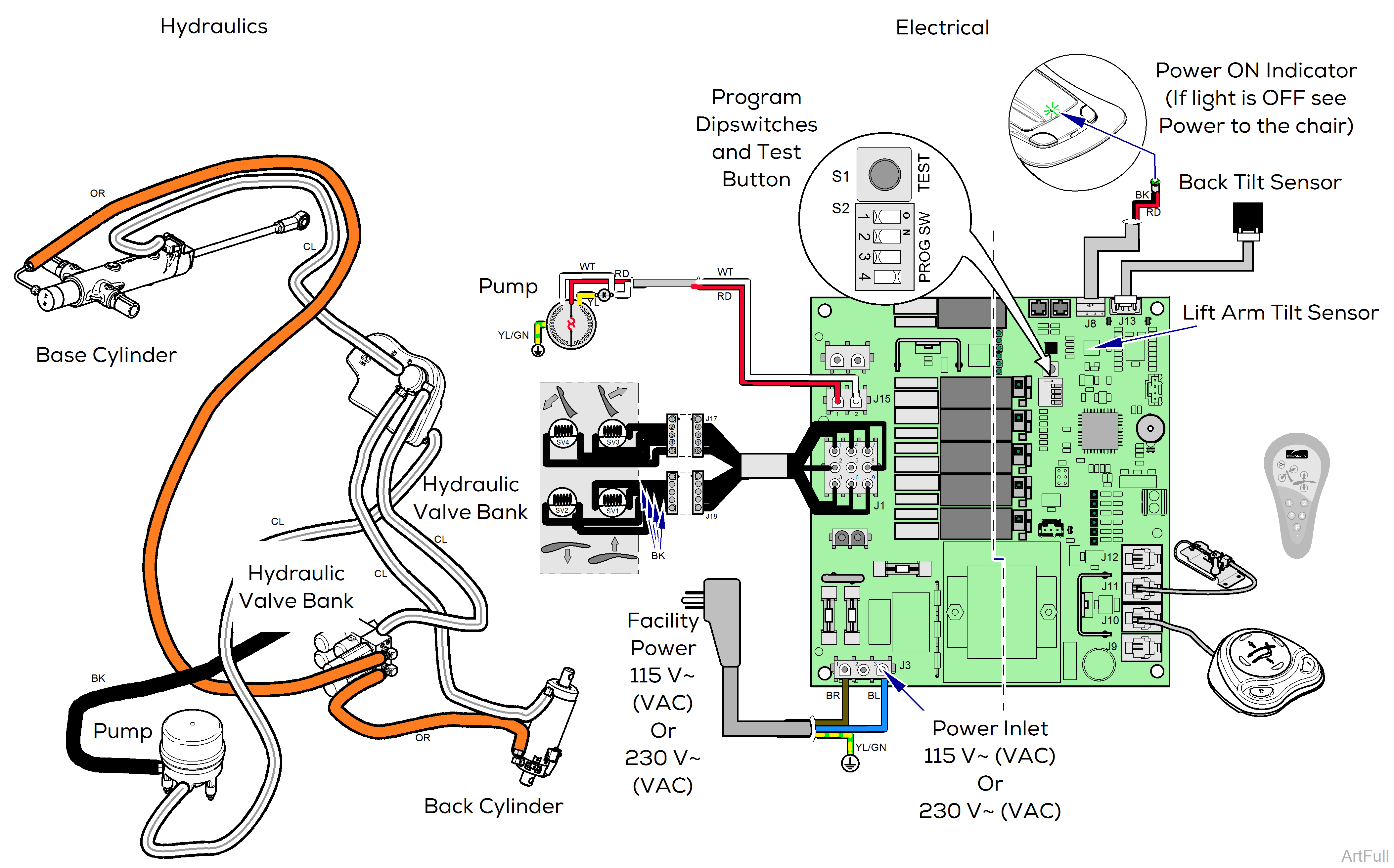
The system
Two tilt sensors (accelerometers) constantly monitor positions, relative to the floor, of the lift arm (base) and the back. This data is transmitted to the PC board where the software uses it locate the ends of travel points, calculate working values for these points and store these values in memory.
Dipswitch #4 must be moved to the On position to perform calibration.
Dipswitch #4 must be moved to the Off position for normal operation of the chair.
Always cycle the power off/on when changing the dipswitch position.
Chair Calibration
Calibration is an automated routine of the full range of back and seat movements performed to collect, calculate and store data that expresses this motion in the software’s language and then test the results of the routine. Refer to: Chair Calibration Procedure
Manual Calibration
Manual calibration is a modified version of the chair calibration routine, allowing a user to manually set the travel limits of the seat and back for a customized application.
Refer to: Manual Chair Calibration Procedure
Override Function
The wireless remote has an override function, activated by pressing and holding the P button and any arrow button simultaneously. The override function allows a user to raise or lower the seat or back any time the chair is powered. The override function is directed by the user’s button inputs, which override software directed inputs.
Relevant voltage readings:
•115 V~ (VAC) at J3, Power inlet. Read pins 1 & 3
•115 V~ (VAC) at J15, Pump Motor. Read pins 1 & 2
•115 V~ (VAC) at J1 Hydraulic Valve Bank
▪Read pins 7 + 1, 2, or 3 for Back Up
▪Read pins 8 + 1, 2, or 3 for Back Down
▪Read pins 9 + 1, 2, or 3 for Base Up
▪Read pins 6 + 1, 2, or 3 for Base Down
Look at LEDs for the J9 - 12, Control (Comm) Communication Ports to verify power and activity
LED ON = device connection is seen by software
LED BLINKING = comm port is receiving a command from a user
