Ultra Chair Back Potentiometer Test and Repair
1.Remove seat upholstery, Refer to:Upholstery.
If necessary, back positioning potentiometer, Item 1, can be over-ridden in order to operate Back section. While holding down Program button on membrane or foot switch, press Back Down directional button.
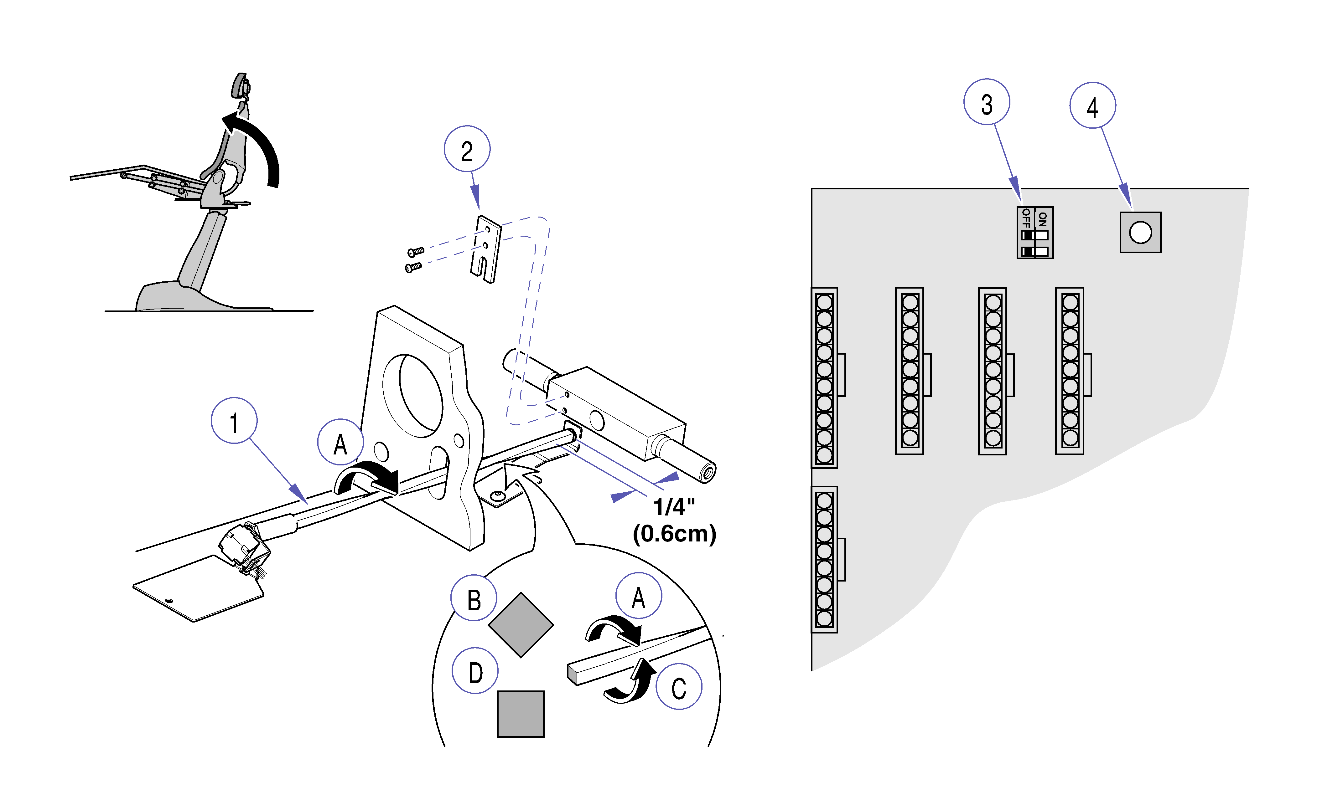
2.Place chair back in full Back Down position and disconnect lift spring, Item 2, on patient’s right side.
Unplug chair power cord before removing covers or working on chair. Failure to comply could result in personal injury.
3.Unplug chair power cord and remove hydraulic cover, see Covers.
4.Remove sensor dog, Item 3, two screws.
5.Disconnect plug connector, Item 4, from back positioning potentiometer, Item 1.
6.Remove back sensor bracket, Item 5 with potentiometer, Item 1, and sensor shaft, Item 6.
7.Disconnect sensor shaft, Item 6, from rubber coupling, Item 7, then remove coupling from potentiometer, Item 1.
8.Remove mounting nut, Item 8, lockwasher, Item 9, and potentiometer, Item 1, from back sensor bracket, Item 5.
Do not over-tighten nut when mounting potentiometer to back sensor bracket or potentiometer could be damaged.
1.Secure potentiometer, Item 1, to back sensor bracket, Item 5, with lockwasher, Item 9, and mounting nut, Item 8.
Larger diameter end of sensor shaft, Item 6, connects to rubber coupling, Item 7.
2.Insert rubber coupling, Item 7, onto shaft of potentiometer, Item 1, and connect sensor shaft, Item 6.
3.Install plug connector, Item 4, to potentiometer, Item 1.
4.Install potentiometer, Item 1, and sensor shaft, Item 6, on chair, inserting small end of shaft into outboard bracket, Item 10.
5.Secure back sensor bracket, Item 5, with screw and install lift spring, Item 2.
Use caution to prevent electrical shock with chair plugged into outlet. Electrical components and connections are exposed.
1.Plug chair power cord into outlet.
2.While holding down Program button on membrane or foot switch, press Back Up directional button, raising back to full up position.
3.Rotate sensor shaft, Item 1 in Back Potentiometer -2 illustration, Fully Clockwise (A) until it stops, then continue to turn it until the corner (B) of the shaft is facing upward.
Back Potentiometer - 2
4.Turn sensor shaft, Item 1, counter-clockwise (C) to the first flat surface (D) and install sensor dog, Item 2, two screws.
5.Unplug chair power cord, place SW1 switches, Item 3, both in On position.
6.Press Calibration button, Item 4.
Chair automatically completes two cycles during Calibration. First cycle finds the extreme end of travel sensor settings. Second cycle checks to assure settings have been stored and can be recalled by software.
7.Unplug chair power cord, Place SW1 switches, Item 3, to desired operating position. Refer to: SW1 Switch Settings. Plug in chair power cord, check Back Up and Back Down positions using directional buttons on foot or membrane switch.
Back Up and Down positions should almost reach maximum travel. If necessary, readjust potentiometer.
8.Install hydraulic cover, Refer to:Covers.
9.Install seat upholstery, Upholstery.
Back Potentiometer - 3
1.Remove seat upholstery, Upholstery.
If necessary, back positioning potentiometer, Item 1, can be over-ridden in order to operate Back section. While holding down Program button on membrane or foot switch, press Back Down directional button.
2.Place chair back in full Back Down position.
Unplug chair power cord before removing covers or working on chair. Failure to comply could result in personal injury.
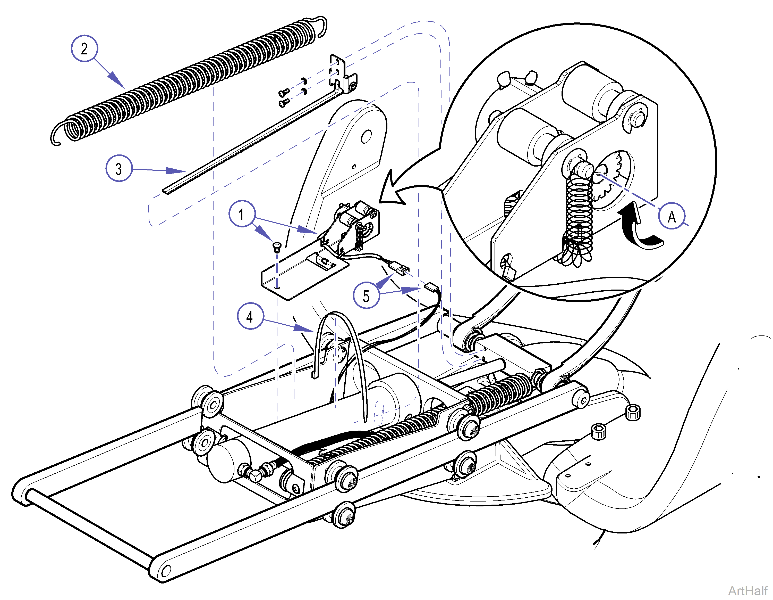
3.Unplug chair power cord, disconnect lift spring, Item 2, on patient’s right side and remove hydraulic cover, Refer to:Covers.
4.Remove gear rack, Item 3, two screws.
5.Cut wire tie, Item 4, and disconnect wire harness plugs, Item 5.
6.Remove potentiometer assembly, Item 1, one screw.
1.Connect chair to supply power. While holding down the Program button on membrane or foot switch press Back Up switch and raise back all the way Up to its mechanical stop position.
Assure power is disconnected from chair before attempting to work on unit.
2.Disconnect power supply to chair.
3.Install potentiometer assembly, Item 1.
4.Connect wire harness plugs, Item 5, and secure hydraulic hoses and wire to seat cylinder with wire tie, Item 4.
5.Rotate (A) potentiometer spur gear, see arrow, until it stops at end of travel.
6.Assure chair back is positioned all the way Up, to mechanical stop position, before inserting gear rack. When gear rack is inserted potentiometer will be adjusted to correct travel.
7.Insert gear rack, Item 3, through access hole of face plate on hydro-glide assembly, engaging gears on rack with spur gear (A) on potentiometer assembly, Item 1.
8.Secure gear rack, Item 3, to yoke block, two screws.
9.Connect right hand (patient’s) lift spring.
Use caution to prevent electrical shock with chair plugged into outlet. Electrical components and connections are exposed.
10.Place both switches on SW1 to On position, Plug chair into outlet, and run a Calibration Mode, Refer to: SW1 Switch Settings.
11.After Calibration is completed, Unplug chair from outlet, place SW1 switches to previous settings, Plug chair into outlet, and run various functions to check operation.
12.Unplug chair and install cover, then plug chair back into outlet.
