Midmark® Dental Lights Control PC Board Test and Repair
|
Mounted To |
Ceiling, Chair, Track, Universal and Wall/Cabinet |
| Serial Number | NW, RE and V Serial Number Prefixes |
Refer to: Midmark Dental Light User Guide for complete instructions on operating the light. Failure to do so could result in personal injury.
Perform an operational test on the dental light after repair is completed to confirm repair was properly made and that all malfunctions were repaired.
To Test the Light Control PC Board
1.Turn OFF power to the unit.
On some units, end cap removal differs slightly. Also, on some units, both end caps may need removed.
2.Remove screw and arm end cap from light arm channel. Refer to: Light Control PC Board Access Procedures
3.Slide light arm cover backward approximately 12 in. to gain access to light control board.
Do NOT remove the Power Supply and Power to the Light leads from the board as it will be necessary to power up the board to test it.
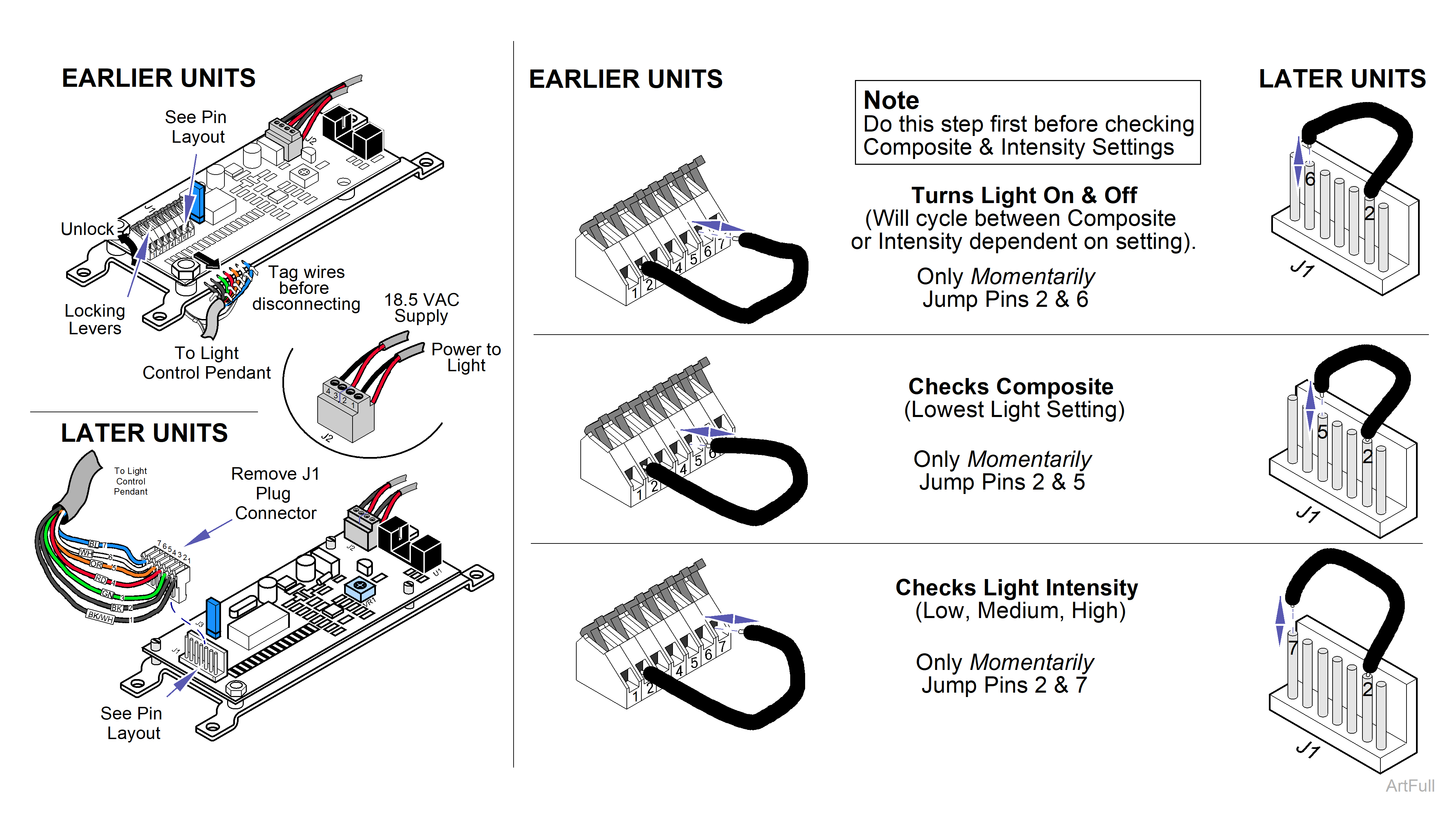
4.Remove J1 Plug Connector. On earlier units, tag the 7 wires, then disconnect them by rotating the lock lever upward.
Use care when testing circuits with the supply power on to prevent injury from electrical shock.
5.Turn on the power to the unit.
The power at the Light Control PC Board should be 18.5 VAC at the J2 plug connector, pins 3 and 4.
6.Check the supply power at the light control PC board at connector J2, pins 3 and 4. There should be 18.5 VAC.
When testing the light with the jumper wire, only momentarily (briefly) touch the pins to energize the specific mode of operation. The light must be on before checking Composite and Light Intensity.
7.Turn ON the light by briefly jumping pins 2 and 6.
8.Jump pins 2 and 5 to check the Composite mode.
9.Jump pins 2 and 7 to check Light Intensity settings. Touch, release, and retouch the pins to go from one setting to another.
