Midmark® Dental Lights Arm Leveling Adjustments
Refer to: Midmark Dental Light User Guide for complete instructions on operating the light. Failure to do so could result in personal injury.
Perform an operational test on the dental light after repair is completed to confirm repair was properly made and that all malfunctions were repaired.
|
Mounted To |
Chair |
| Serial Number | NW, RE and V Serial Number Prefixes |
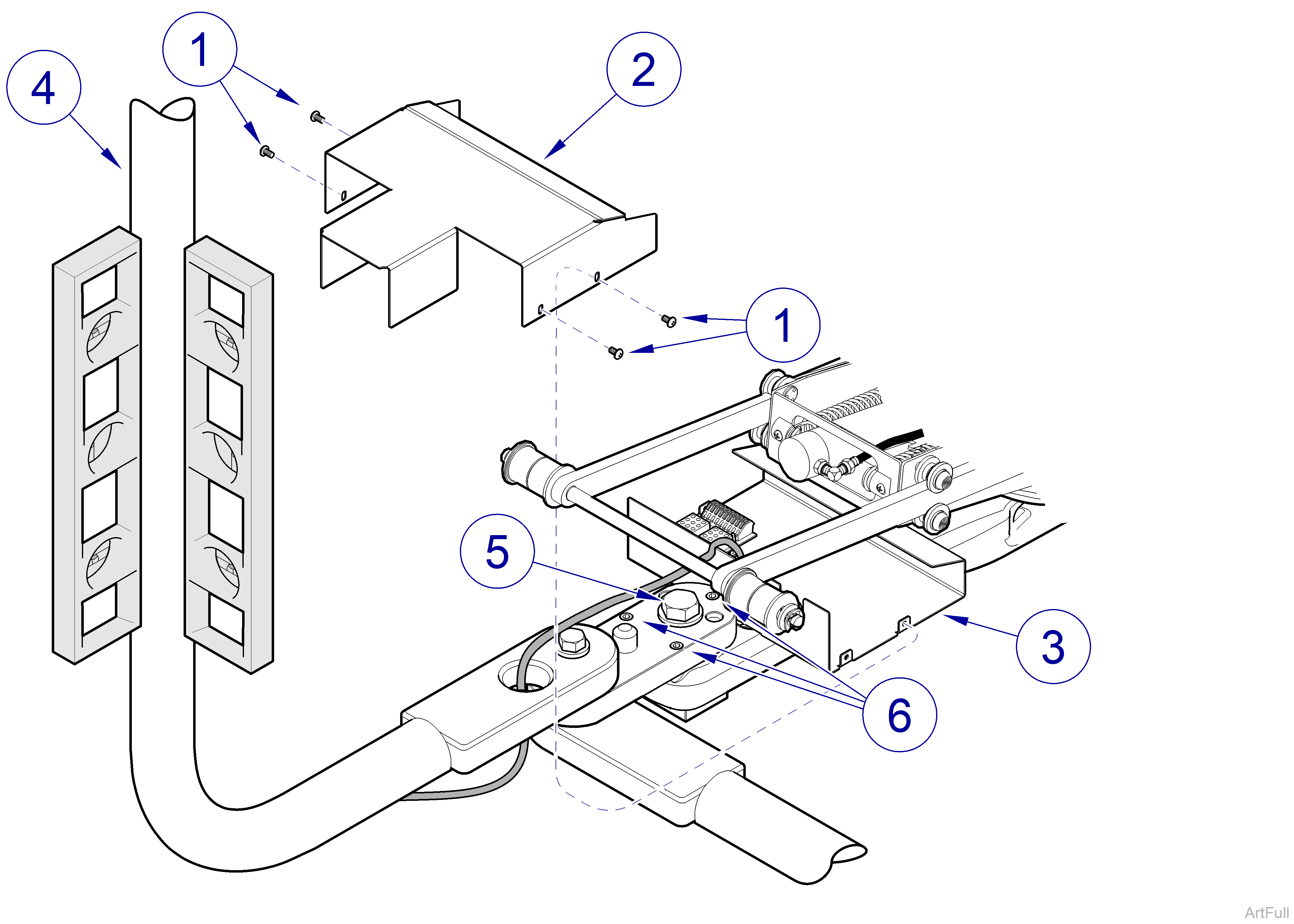
To Level LR Light Arm
If a delivery unit is also mounted on LR mounting bracket with LR light, care must be taken to make sure that leveling light arm does not put delivery unit arms “out-of-level”.
1.Remove four screws (1) and connection cover (2) from connection box (3).
2.Position light arm (4) straight out from foot end of chair as shown in illustration.
3.Tighten screw (5) as necessary.
4.Adjust three leveling screws (6) until light arm is plumb. When checking light arm to ensure it is plumb, place level at two spots on light arm 90° apart.
5.Install connection cover (2) on connection box (3) and secure with four screws (1).
|
Mounted To |
Console |
| Serial Number | NW, RE and V Serial Number Prefixes |
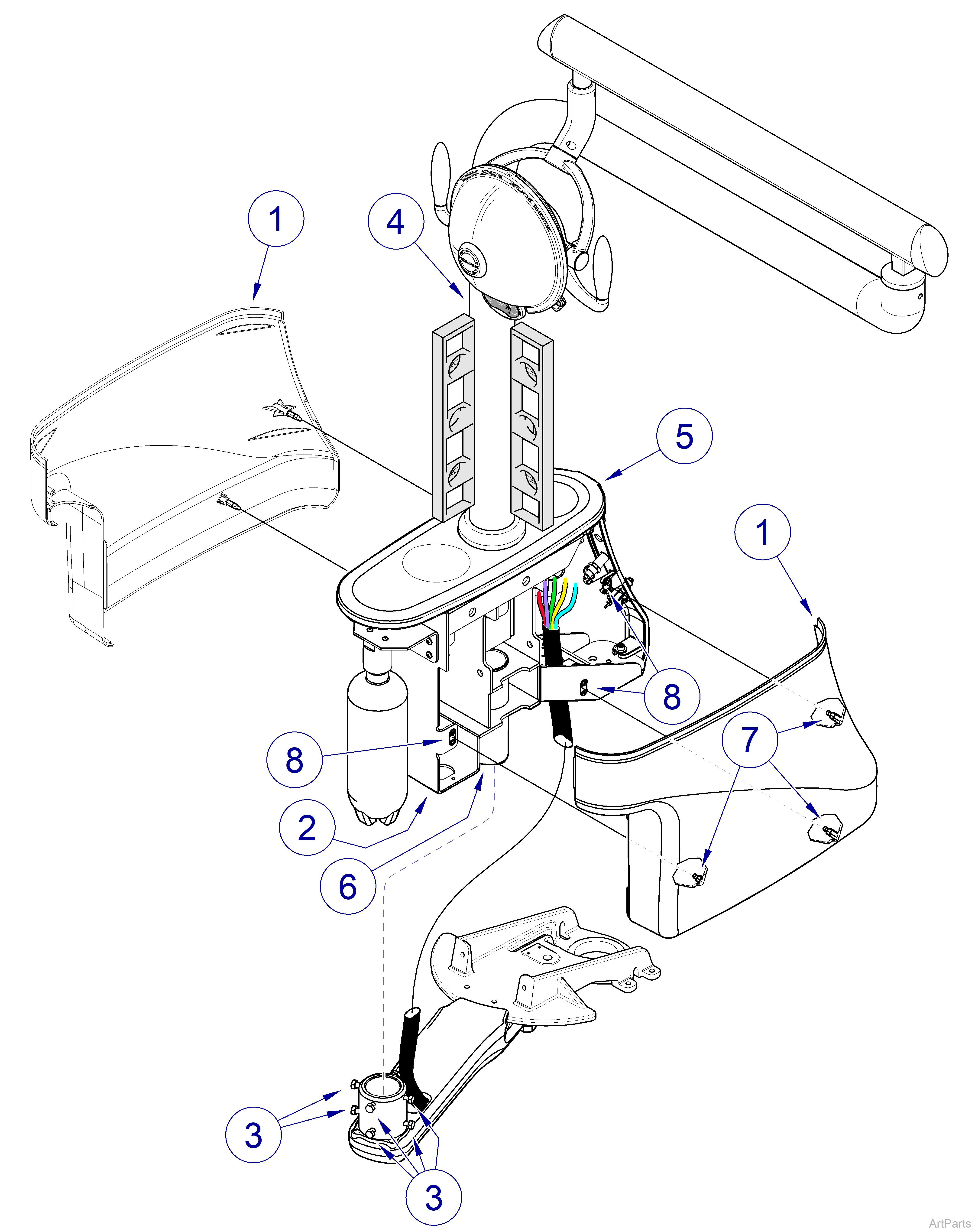
To Level Console Light Arm
If a delivery unit is also mounted on console which has a light system, care must be taken to make sure that leveling light arm does not put delivery unit arms “out-of-level”.
1.Remove LH and RH console covers (1) from console frame (2) by pulling outward on bottom of console covers until they “pop” loose.
2.Loosen eight leveling screws (3) until they are fully retracted.
3.Using a level, position light arm (4) so that it is plumb; then adjust eight leveling screws (3) until they are contacting post (6) of console frame (2).
4.Adjust eight leveling screws (3) as necessary to fine tune leveling of light arm (4). When checking light arm to ensure it is plumb, place level at two spots on light arm 90° apart.
5.Slide top of LH console cover (1) under top cover (5); then align three ball studs (7) on console cover with three stud fasteners (8) on console frame (2).
6.Push gently inward on console cover (1) until it “snaps” into place. Repeat steps 5 and 6 for RH console cover.
|
Mounted To |
Ceiling |
| Serial Number | NW, RE and V Serial Number Prefixes |
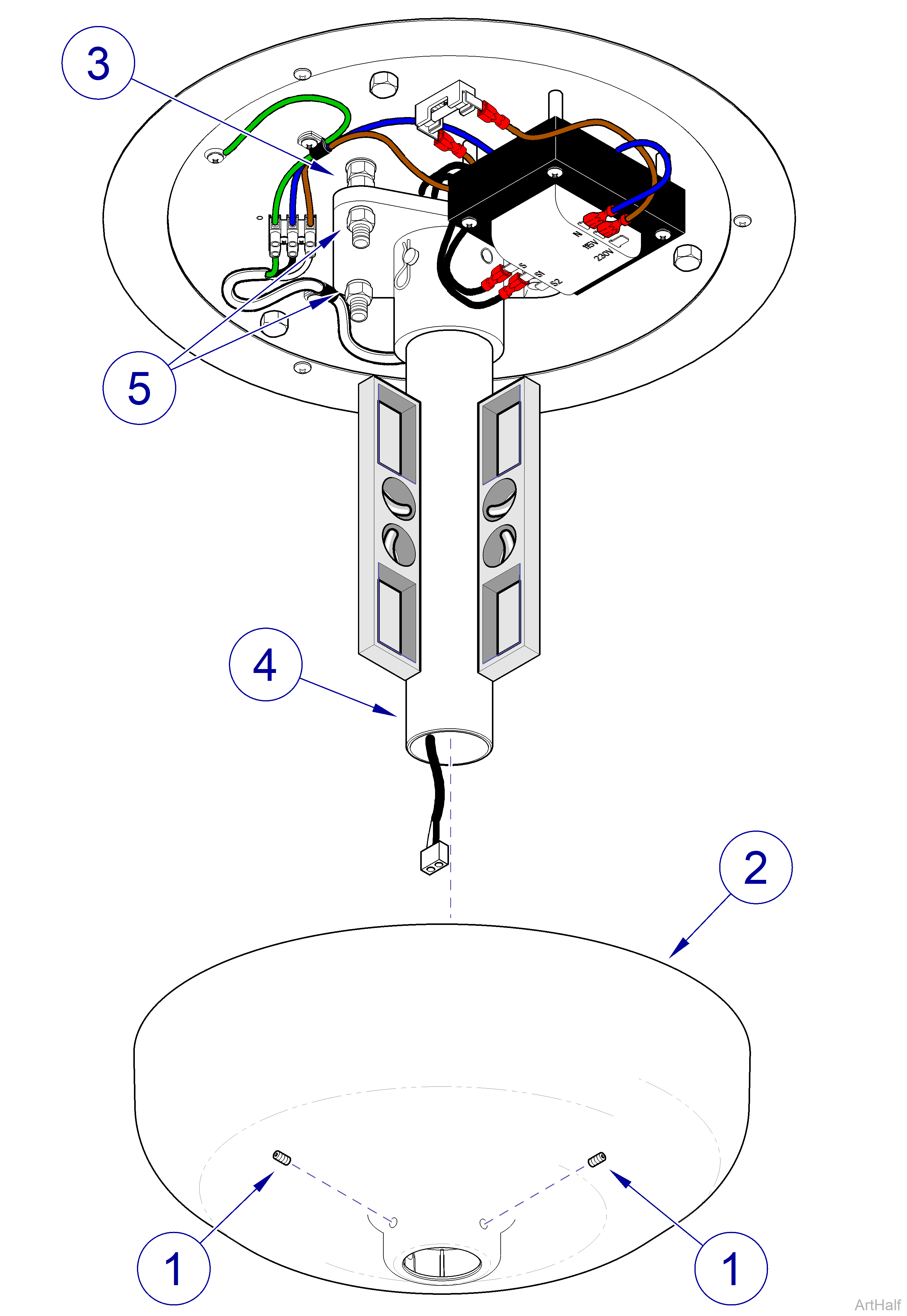
To Level Ceiling Light Arm
Always disconnect electrical power from the unit before removing any of the unit’s covers/shrouds or making any repairs to prevent the possibility of electrical shock. Failure to comply with these instructions could result in severe personal injury or death.
1.Turn OFF facility power breaker so there is no power to light unit.
2.Loosen two setscrews (1) and lower ceiling cover (2) down out of way.
3.Loosen three jam nuts (3).
4.Place level on suspension tube (4) and adjust three hex nuts (5) until suspension tube is plumb; then tighten three jam nuts (3).
5.Position ceiling cover (2) up against ceiling and then secure in position with two setscrews (1).
6.Turn ON facility power breaker so there is power to light unit.
