Midmark® Dental Lights Fuse Access Procedures
Refer to: Operator’s Manual for complete instructions on operating the light. Failure to do so could result in personal injury.
Perform an operational test on the dental light after repair is completed to confirm repair was properly made and that all malfunctions were repaired.
|
Mounted To |
Ceiling |
| Serial Number | NW, RE, and V Serial Number Prefixes |
Always disconnect electrical power from the unit before removing any of the unit’s covers/shrouds or making any repairs to prevent the possibility of electrical shock. Failure to comply with these instructions could result in severe personal injury or death.
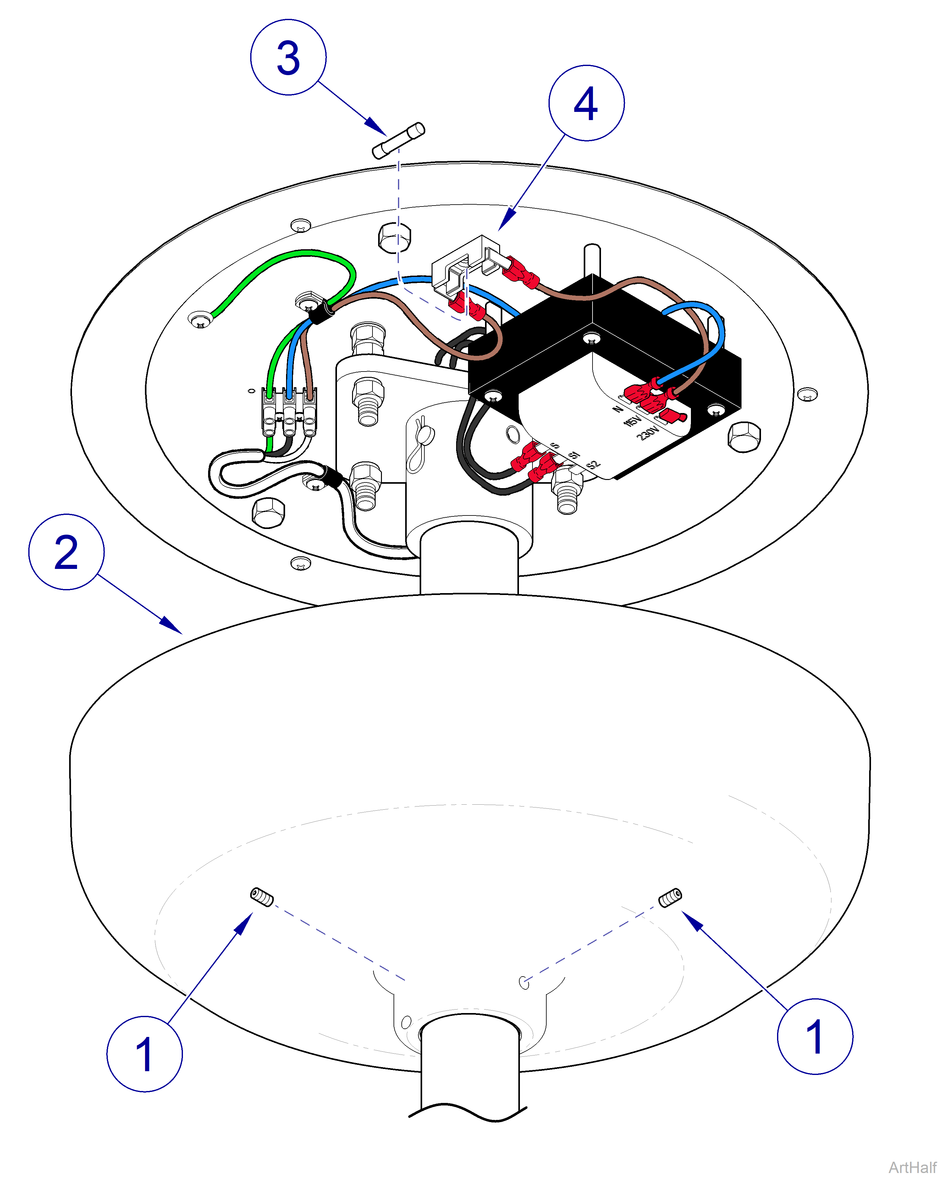
1.Turn OFF facility power breaker so there is no power to light unit.
2.Loosen two setscrews (1) and lower ceiling cover (2) down out of way.
3.Pull fuse (3) out of fuse holder (4).
4.Inspect fuse (3) for any indication it has been blown. Perform continuity check on fuse. If bad, discard fuse.
Refer to: Specifications to ensure correct replacement fuse is used.
1.Insert new fuse (3) in fuse holder (4).
2.Position ceiling cover (2) up against ceiling and then secure in position with two set screws (1).
3.Turn ON facility power breaker so there is power to light unit.
|
Mounted To |
Track |
| Serial Number | NW, RE, and V Serial Number Prefixes |
Always disconnect electrical power from the unit before removing any of the unit’s covers/shrouds or making any repairs to prevent the possibility of electrical shock. Failure to comply with these instructions could result in severe personal injury or death.
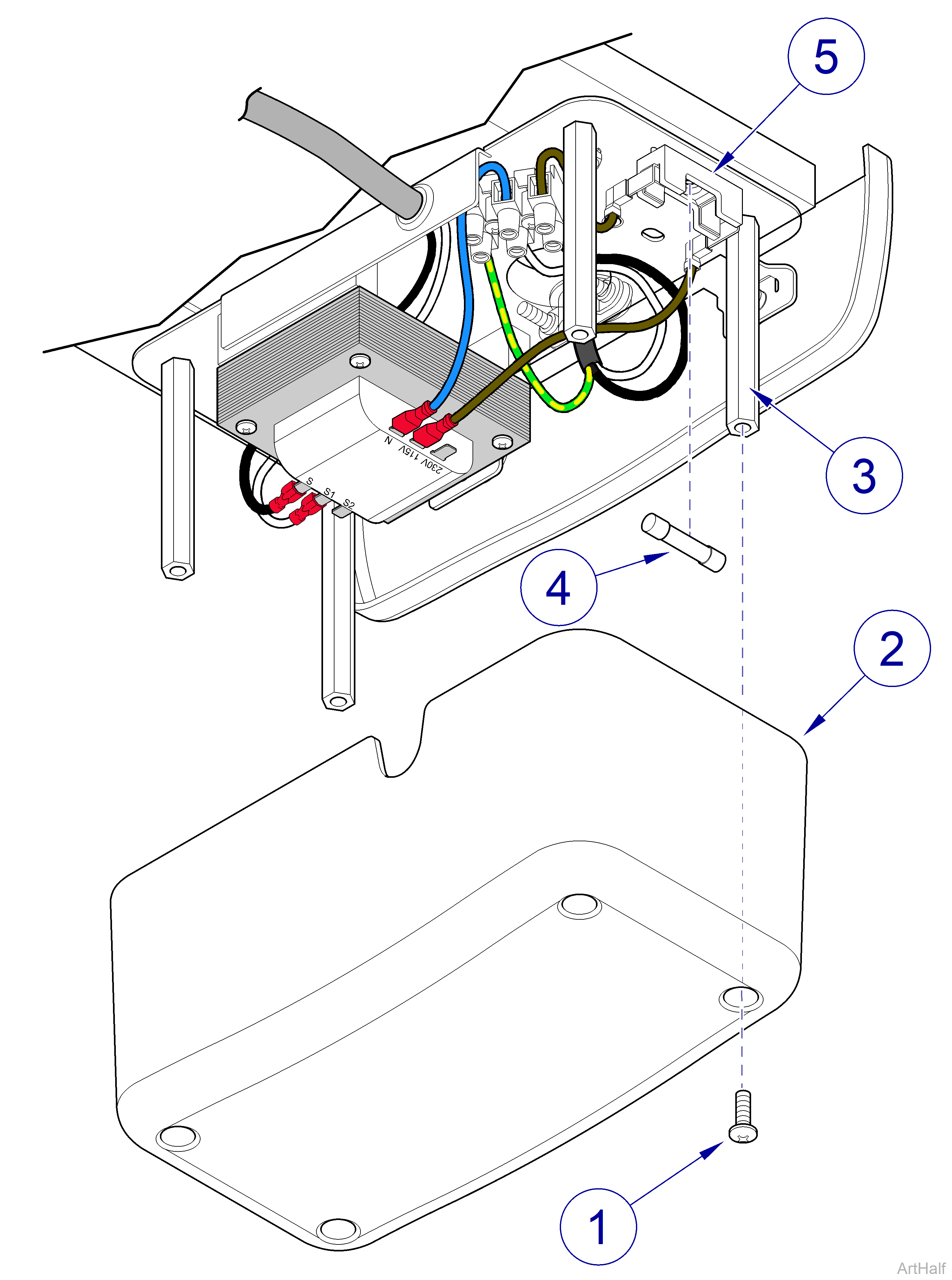
1.Turn OFF facility power breaker so there is no power to light unit.
2.Remove four screws (1) and transformer cover (2) from standoffs (3).
3.Pull fuse (4) out of fuse holder (5).
4.Inspect fuse (4) for any indication it has been blown. Perform continuity check on fuse. If bad, discard fuse.
Refer to: Specifications to ensure correct replacement fuse is used.
1.Insert new fuse (4) in fuse holder (5).
2.Install transformer cover (2) on standoffs (3) and secure with four screws (1).
3.Turn ON facility power breaker so there is power to light unit.
|
Mounted To |
Wall/Cabinet |
| Serial Number | NW, RE, and V Serial Number Prefixes |
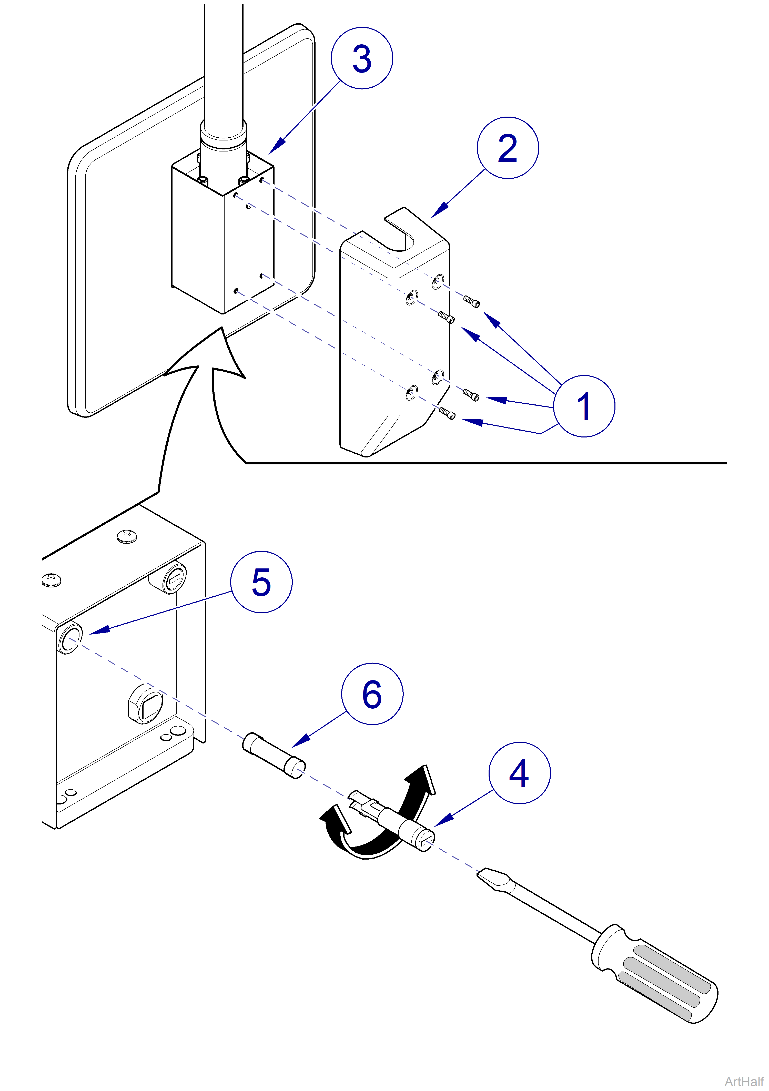
1.If wall unit only, remove four screws (1) and transformer cover (2) from mount assembly (3).
2.Simultaneously push in on fuse cap (4) with a small slotted screwdriver and rotate it 1/4 turn in the counterclockwise direction; then pull fuse cap from fuse holder (5).
3.Pull fuse (6) out of fuse cap (4).
4.Inspect fuse (6) for any indication it has been blown. Perform continuity check on fuse. If bad, discard fuse.
Refer to: Specifications to ensure correct replacement fuse is used.
1.Insert new fuse (6) in fuse cap (4).
2.Simultaneously push fuse cap (4) into fuse holder (5) and rotate it 1/4 turn in clockwise direction to secure it.
3.Install transformer cover (2) on mount assembly (3) and secure with four screws (1).
|
Mounted To |
Universal |
| Serial Number | NW, RE, and V Serial Number Prefixes |
Always disconnect electrical power from the unit before removing any of the unit’s covers/shrouds or making any repairs to prevent the possibility of electrical shock. Failure to comply with these instructions could result in severe personal injury or death.
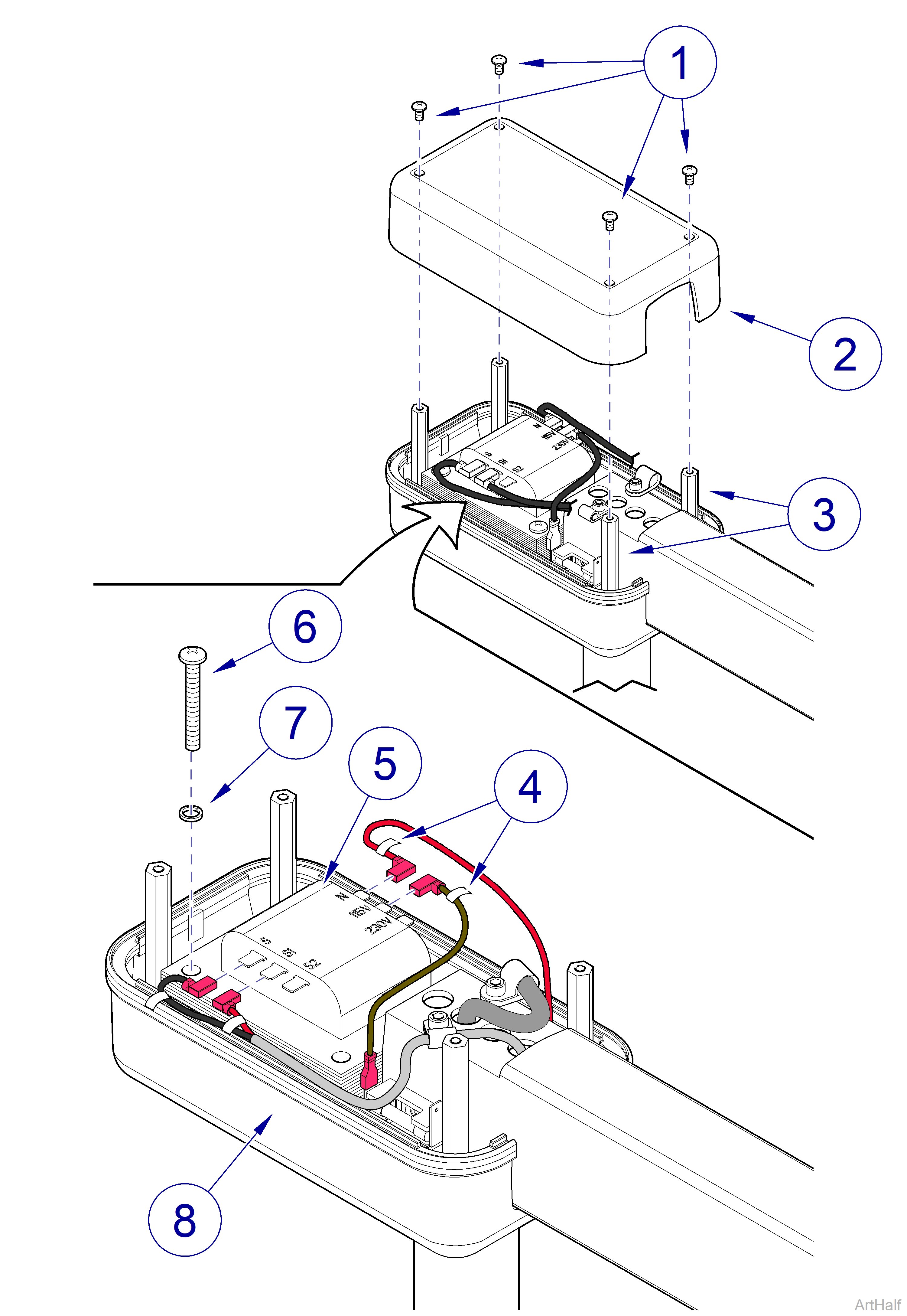
1.Turn OFF facility power breaker so there is no power to light unit.
2.Remove four screws (1) and top transformer cover (2) from standoffs (3).
3.Pull each fuse (4) out of each fuse holder (5).
4.Inspect fuse (4) for any indication it has been blown. Perform continuity check on fuse. If bad, discard fuse.
Refer to: Specifications to ensure correct replacement fuse is used.
1.Insert new fuse (4) in fuse holder (5).
2.Install top transformer cover (2) on standoffs (3) and secure with four screws (1).
3.Turn ON facility power breaker so there is power to light unit.
