Midmark® Dental Lights Auto On Mode Test and Repair
|
Mounted To |
Ceiling, Chair, Track, Universal, and Wall/Cabinet |
| Serial Number | NW, RE, and V Serial Number Prefixes |
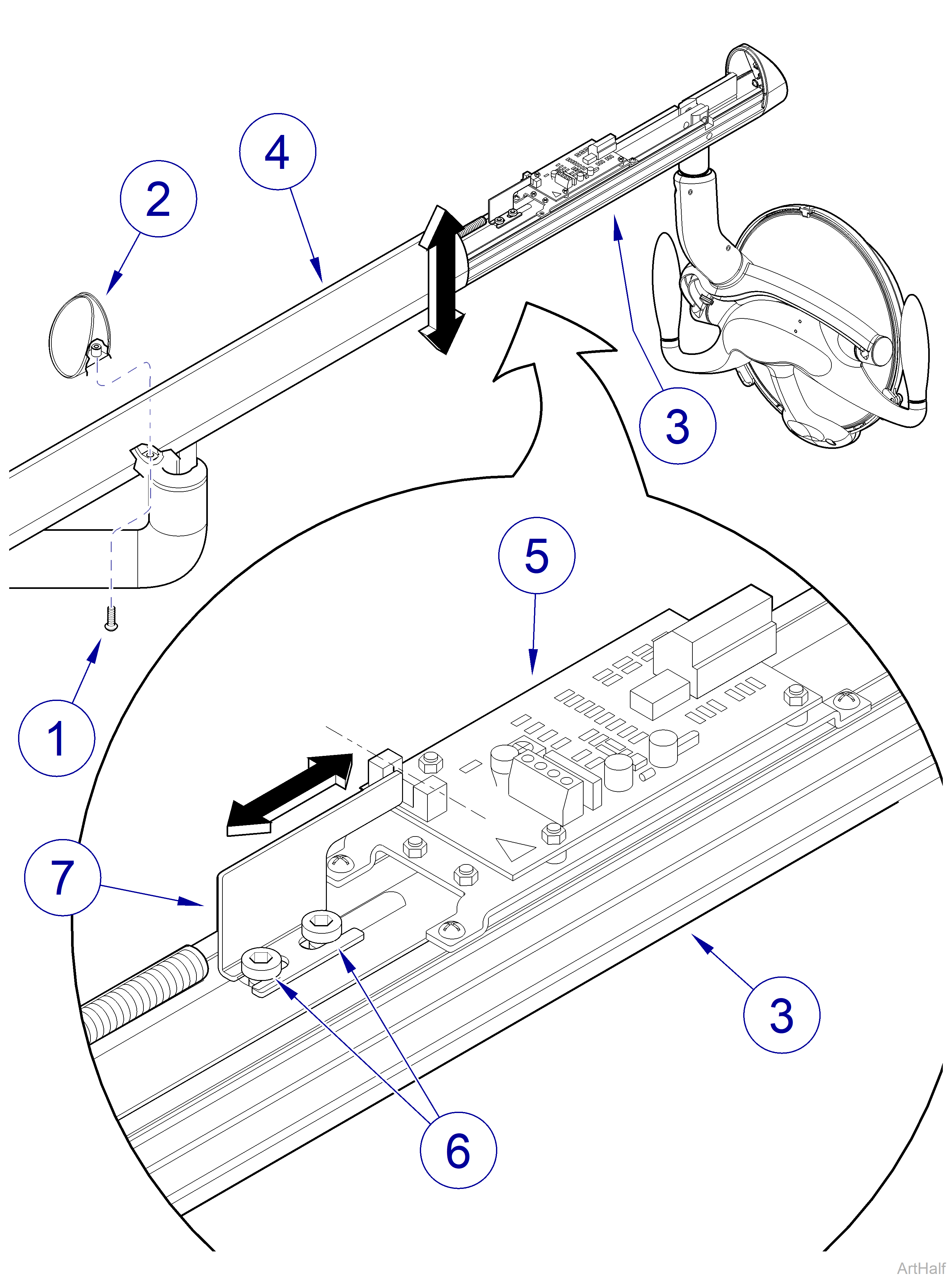
Figure 4-20
Refer to: Operator’s Manual for complete instructions on operating the light. Failure to do so could result in personal injury.
Perform an operational test on the dental light after repair is completed to confirm repair was properly made and that all malfunctions were repaired.
This adjustment allows the user to set desired height (when light arm is being lowered) of light arm at which AUTO ON mode is activated (light automatically turns on).
On some units, end cap removal differs slightly. Also, on some units, both end caps may need removed.
1.Remove screw (1, Figure 4-20) and arm endcap (2, Figure 4-20) from light arm (3, Figure 4-20).
2.Slide light arm cover (4, Figure 4-20) backward approximately 14 in. (35.5 cm) to gain access to light control board (5, Figure 4-20)
3.Press POWER button until light is in AUTO ON mode.
Consult the user of the light to determine the preferred AUTO ON height.
4.Position light arm (3, Figure 4-20) at desired height for AUTO ON mode to activate; hold light arm in this position during next step.
5.Loosen two screws (6, Figure 4-20) and slide trigger (7, Figure 4-20) all the way out; then slowly slide trigger in until lighthead turns on (at set point line). Secure trigger in this position by tightening two screws (6, Figure 4-20).
6.Raise and lower light arm (3, Figure 4-20) to verify set point of AUTO ON mode is set as desired. Repeat steps 4 and 5 as necessary.
7.Slide light arm cover (4, Figure 4-20) back onto light arm (3, Figure 4-20) fully.
8.Install arm endcap (2, Figure 4-20) on light arm (3, Figure 4-20) and secure with screw (1, Figure 4-20).
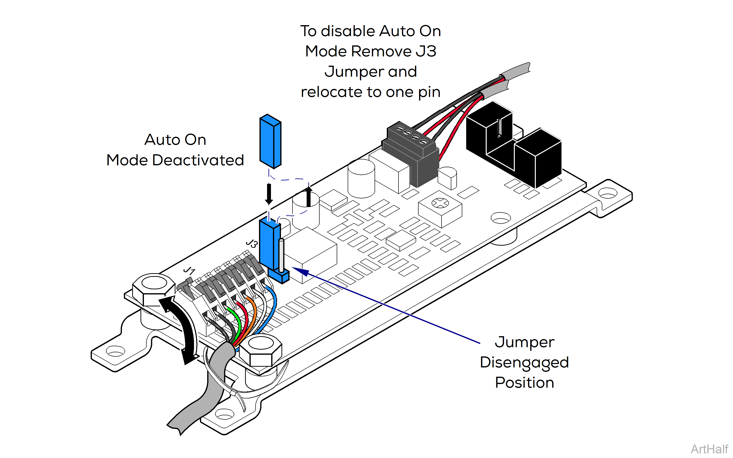
Figure 4-23
1.Turn OFF power to the unit.
On some units, end cap removal differs slightly. Also, on some untis, both end caps may need removed.
2.Remove screw (1, Figure 4-20) and arm end cap (2, Figure 4-20) from light arm channel (3, Figure 4-20).
3.Slide light arm cover (4, Figure 4-20) backward approximately 12 in. to gain access to light control board.
To prevent loss of J3 Jumper when in the Disabled mode, assure the jumper is affixed to one of the two pins on J3 connector.
4.To disable the Auto On Mode, remove the Jumper (Figure 4-23) from J3, two pin connector, and insert it on just one of the pins.
