M9/M11 Sterilizer Fill Mode Theory of Operation
To prevent risk of shock always disconnect power before removing covers or performing any service procedure.
Some procedures require power to be connected with covers removed. Line voltage is present. Use extreme caution to prevent electric shock.
This illustrations call out the components that are energized / monitored during the Fill Mode. Refer to the dropdowns for detailed descriptions of the Fill Mode.
|
Model |
M9/9D -020 thru -022, -033, -034 |
M11/11D -020 thru -022, -033, -034 |
| Serial Number | All | All |
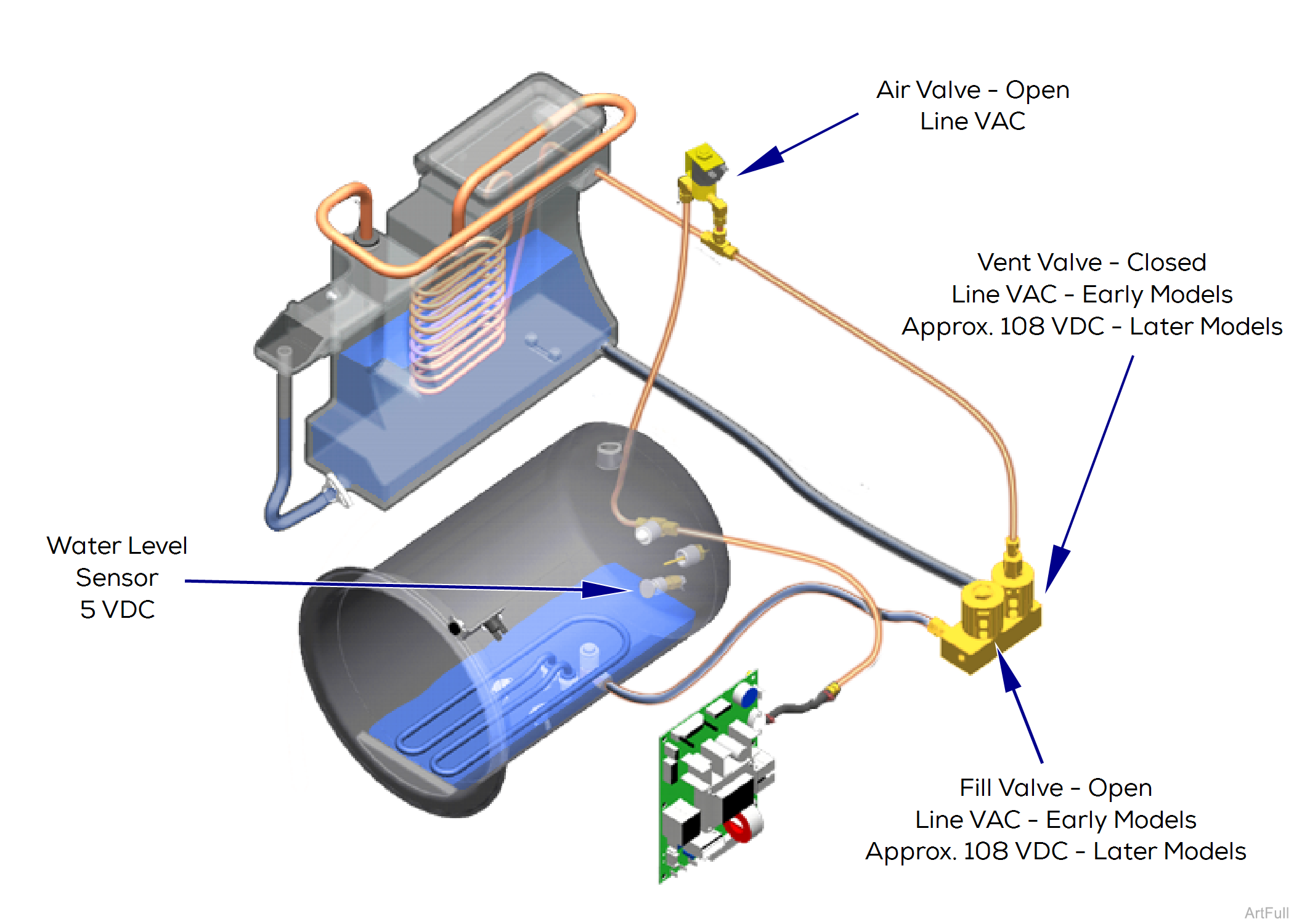
During the Fill Mode, water flows from the reservoir thru the fill valve into the chamber.
All electrical current is supplied thru the two high-limit thermostats on bottom of chamber. Refer to: Power Up Mode for further detail.
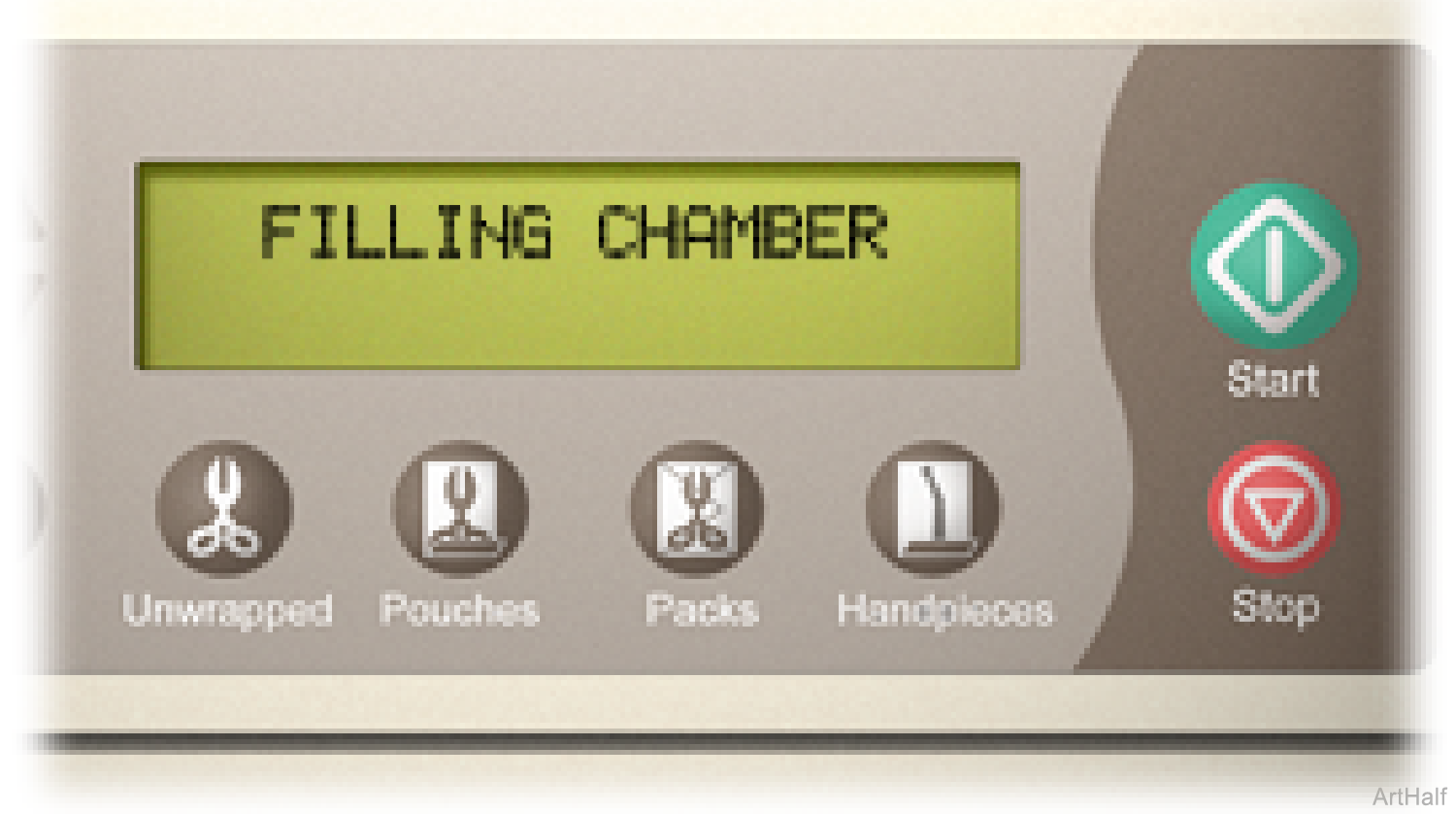
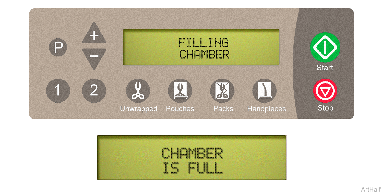
During the Fill Mode, the display panel will show:
Throughout the Fill Mode, line voltage is supplied to the normally closed air valve. When energized, the air valve opens. This allows air to pass thru the valve so that water can flow from the reservoir.
Throughout the Fill Mode, voltage is supplied to the normally open vent valve. When energized, the vent valve closes. This prevents water from flowing back into the reservoir thru the vent valve.
During the Fill Mode, voltage is supplied to the normally closed fill valve. When energized, the fill valve opens allowing water to flow into the chamber.
When the water level in the chamber reaches the water level sensor, the PC Board stops the current flow to the fill valve. This allows the valve to close, stopping the flow of water into the chamber.
Throughout the Fill Mode, 5 VDC is supplied to the water level sensor. When the water level in the chamber reaches the sensor, a circuit is completed and current flows back to the PC Board.
When the 5 VDC from the water level sensor is detected, the PC Board stops the current flow to the fill valve.
|
Model |
M9 -040 thru -043 | M9D -042 | M11 -040 thru -043 |
| Serial Number | All | All | All |
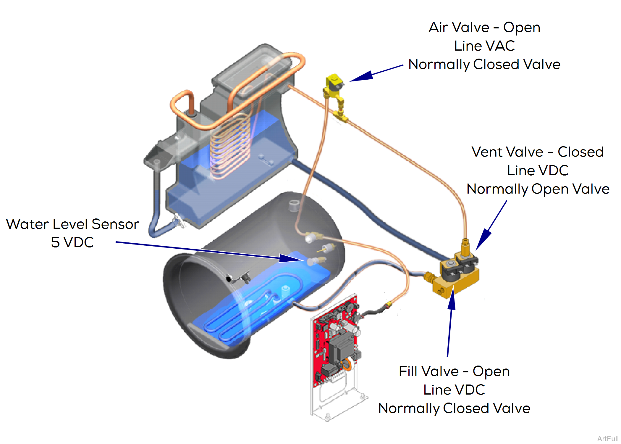
During the Fill Mode, water flows from the reservoir thru the fill valve into the chamber.
All electrical current is supplied thru the two high-limit thermostats on bottom of chamber. Refer to: Power Up Mode for further detail.
Throughout the Fill Mode, line voltage is supplied to the normally closed air valve. When energized, the air valve opens. This allows air to pass thru the valve so that water can flow from the reservoir.
Throughout the Fill Mode, voltage is supplied to the normally open vent valve. When energized, the vent valve closes. This prevents water from flowing back into the reservoir thru the vent valve.
During the Fill Mode, voltage is supplied to the normally closed fill valve. When energized, the fill valve opens allowing water to flow into the chamber.
When the water level in the chamber reaches the water level sensor, the PC Board stops the current flow to the fill valve. This allows the valve to close, stopping the flow of water into the chamber.
Throughout the Fill Mode, 5 VDC is supplied to the water level sensor. When the water level in the chamber reaches the sensor, a circuit is completed and current flows back to the PC Board.
When the 5 VDC from the water level sensor is detected, the PC Board stops the current flow to the fill valve.
