244 Table Tilt Up / Down Function Troubleshooting
Power To The Hand Control
Refer to: Power To The Table for description of current flow to the hand control.
Signal Voltage
The hand control continuously supplies approximately 5 VDC signal voltage to the control box thru separate wires for each function.
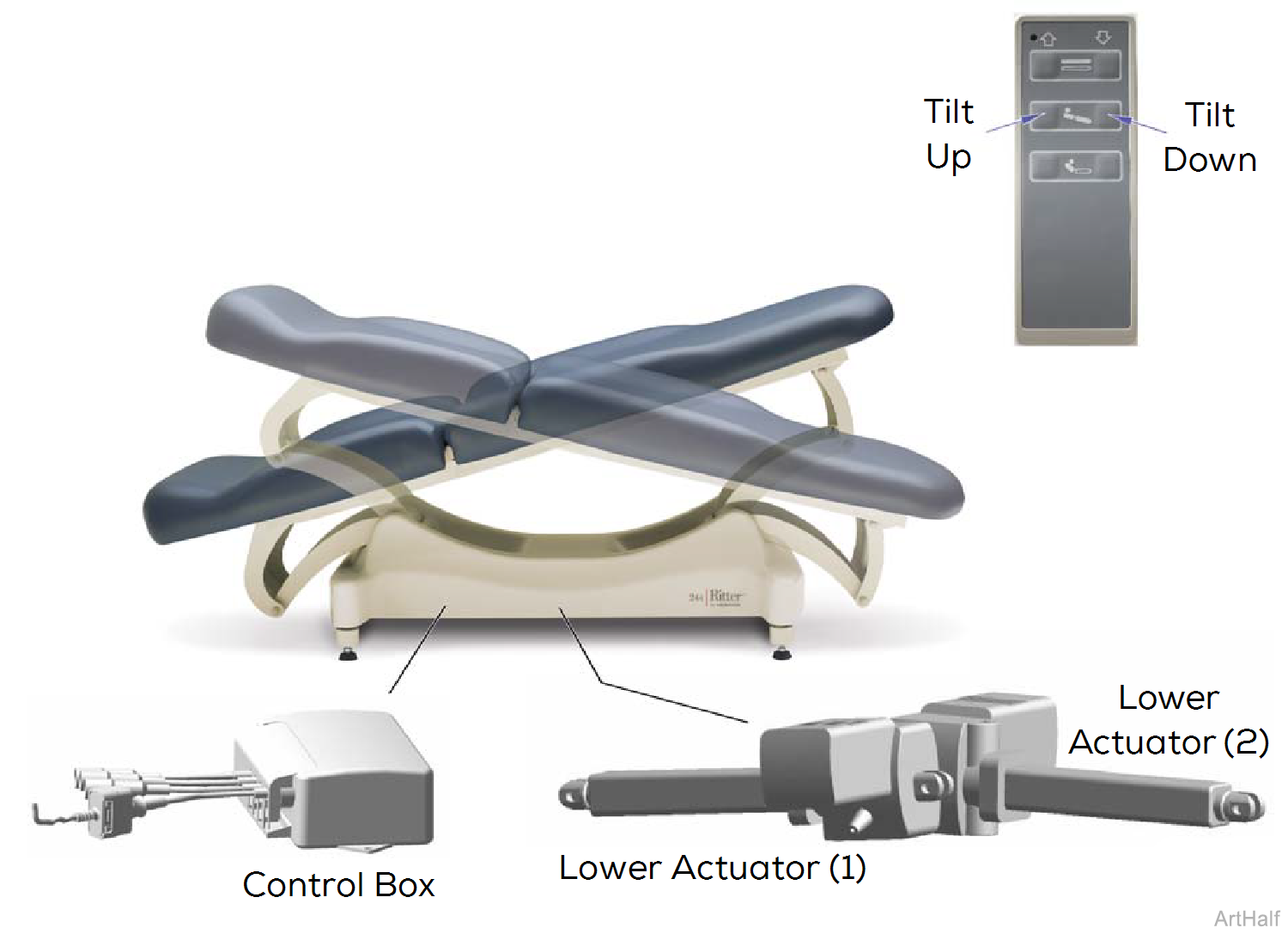
Tilt Up Operation - Foot-end Up
When the Tilt Up button is pressed, the circuit for this function opens, stopping the flow of signal voltage to the control box. When the signal voltage for the Tilt Up function is removed, the control box supplies 24 VDC to both lower actuators.
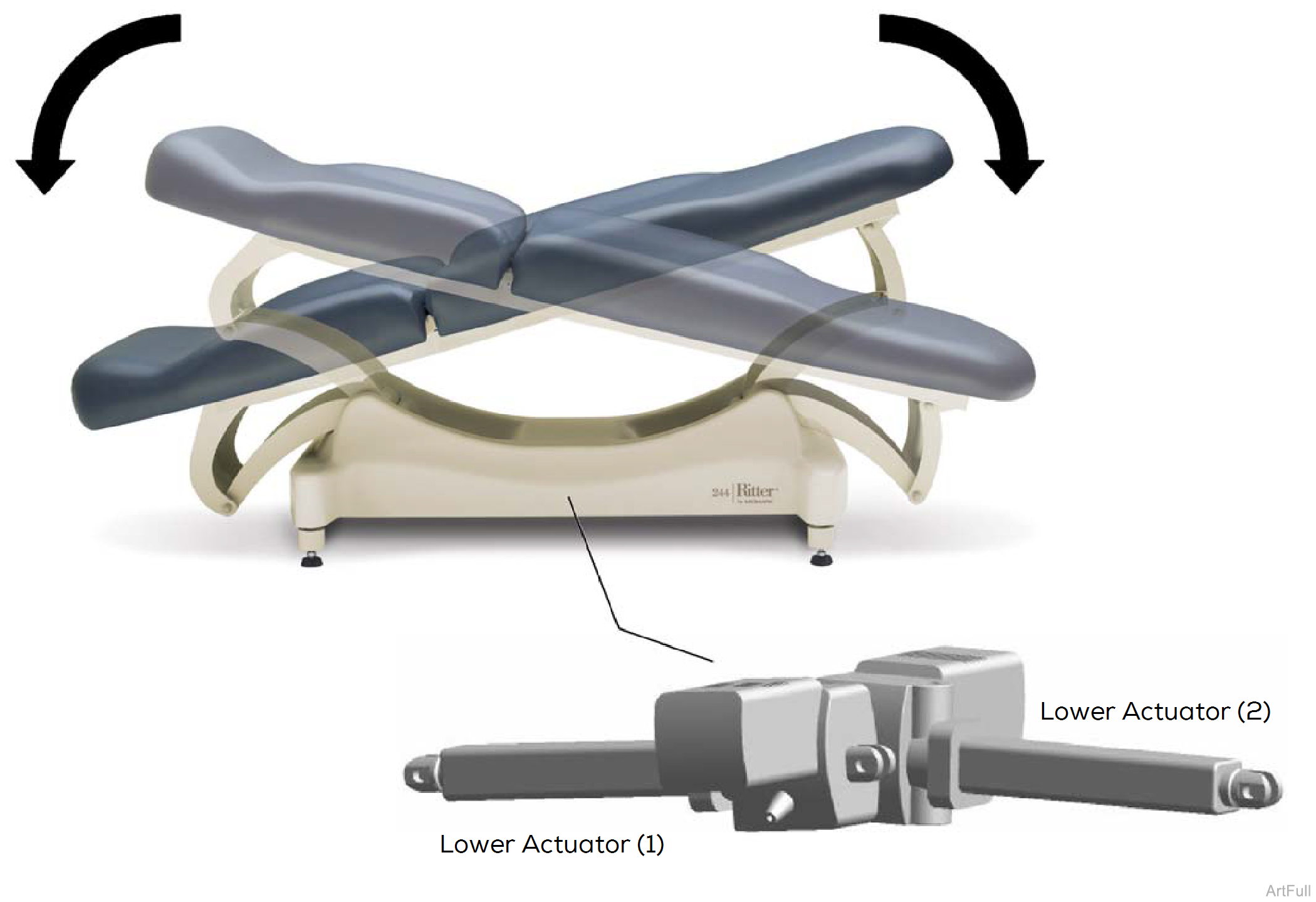
Lower actuator (1) retracts, and lower actuator (2) extends, raising the foot-end of the table.
Both actuator motors run until
1.Hand control button is released.
2.Lower actuator (1) is fully retracted. Lower actuator (2) is fully extended. Internal limit switches not serviceable.
Tilt Down Operation - Foot-end Down
When the Tilt Down button is pressed, the circuit for this function opens, stopping the flow of signal voltage to the control box. When the signal voltage for the Tilt Down function is removed, the control box supplies 24 VDC to both lower actuators.
Lower actuator (1) extends, and lower actuator (2) retracts, lowering the foot-end of the table.
Both actuator motors run until
1.Hand control button is released.
2.Lower actuator (1) is fully extended. Lower actuator (2) is fully retracted. Internal limit switches not serviceable.

1.Does the Back function work? If Yes, go to step 2. If No, Refer to: Power To The Table
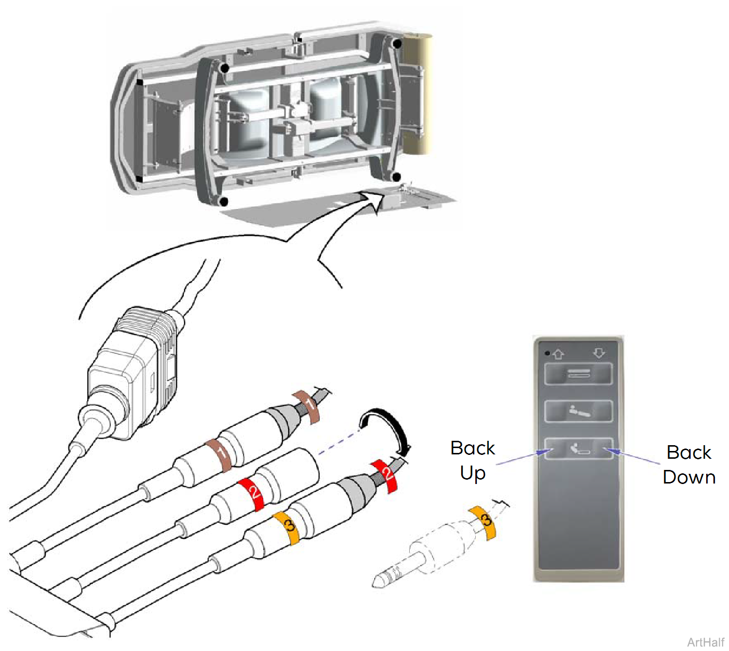
2.Perform Control Box / Lower Actuator Test
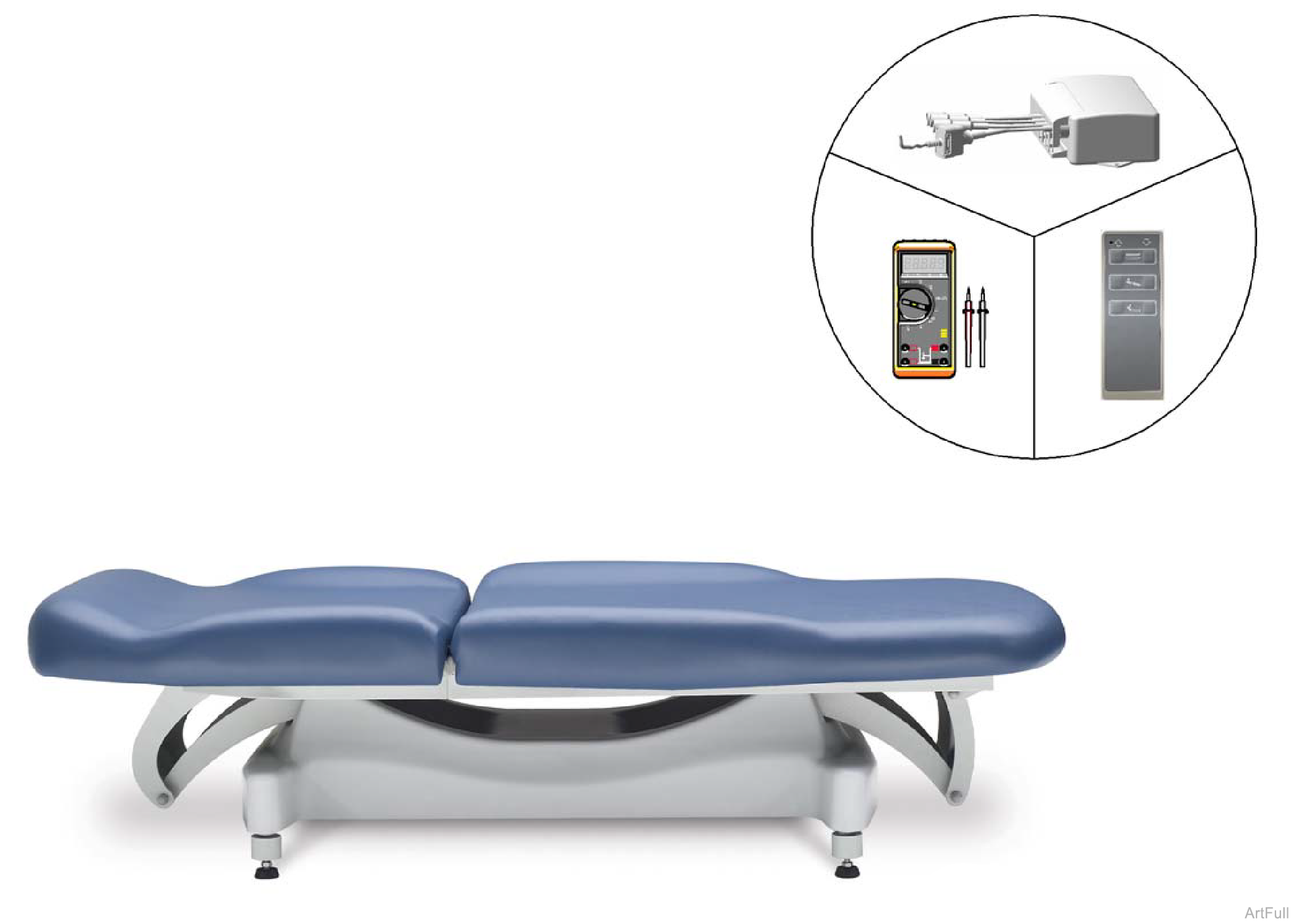
1.If head-end drifts down replace Lower Actuator (1).
2.If foot-end drifts down replace Lower Actuator (2).
The power cord must be plugged in, and the power switch must be ON (I) during these tests.
Keep the area around the table clear! The table will move when performing Steps 2 and 3.
1.Remove bottom cover.
2.Disconnect lower actuator wire (1). Run Tilt Up and Tilt Down functions briefly. If actuator (2) makes loud grinding noise replace lower actuator (2). If actuator (2) sounds OK reconnect lower actuator wire (1).
3.Disconnect lower actuator wire (2). Run Tilt Up and Tilt Down functions briefly. If actuator (1) makes loud grinding noise replace lower actuator (1). If actuator (1) sounds OK reconnect lower actuator wire (2).
The power cord must be plugged in, and the power switch must be ON (I) during these tests.
1.Remove bottom cover.
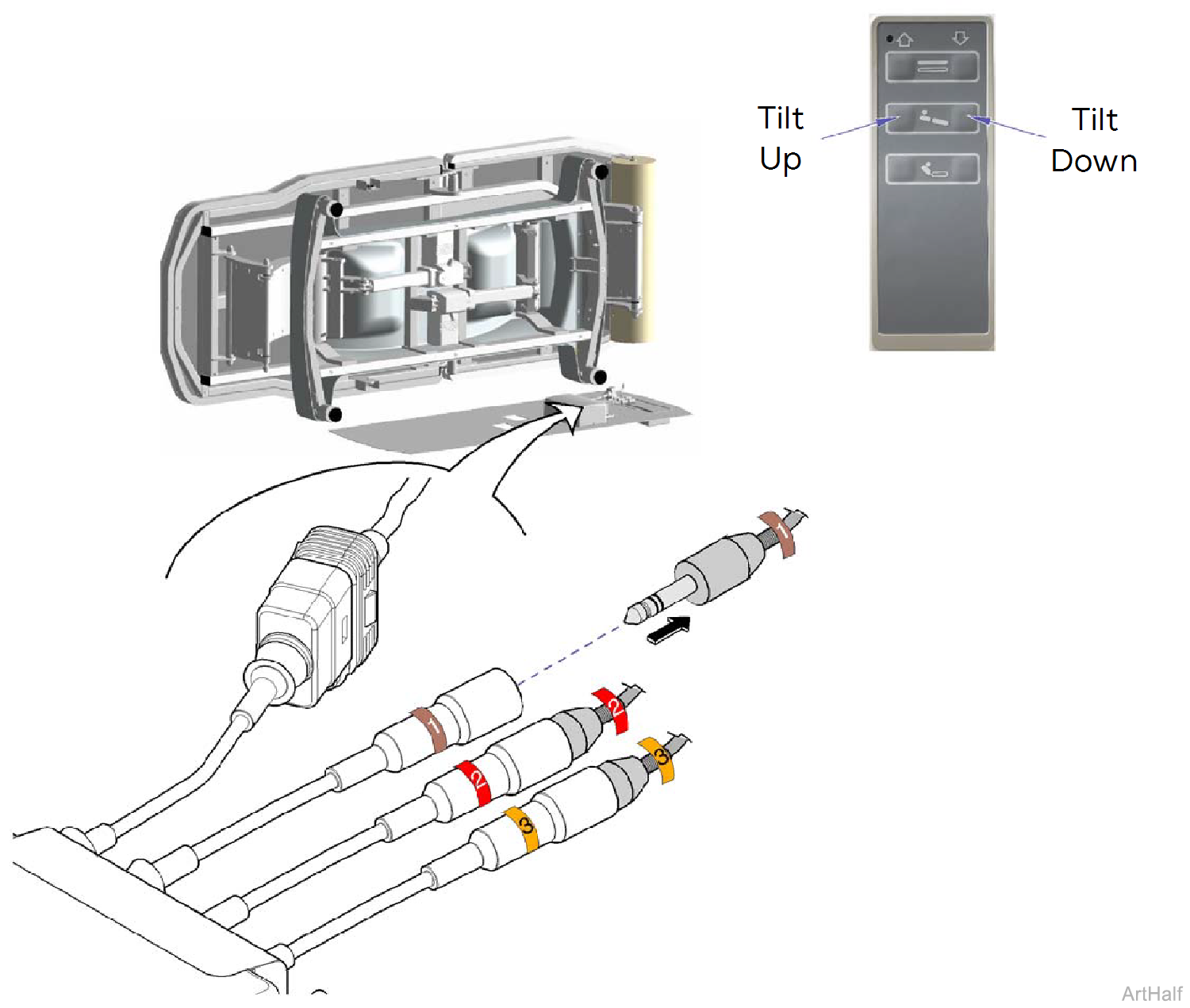
2.Unplug back actuator wire (3). Connect lower actuator wire (2) to control box wire (3).
Keep the area around the table clear! The table may move when performing step 3.
3.Press the Back Up button briefly, then release. Press the Back Down button briefly, then release. Does lower actuator move when buttons are pressed? If Yes, lower actuator is OK. If No, replace actuator. If both lower actuators are OK Go to Step 5.
4.Connect lower actuator wire (1) to control box wire (3). Then, repeat Step 3.
5.Reconnect actuator wires 1, 2, and 3 to corresponding control box wires.
6.Perform Signal Voltage Test: Tilt Function.
Meter should indicate approximately 5 VDC, when hand control button is released. If not, Refer to: Limit Switch Circuit Test.
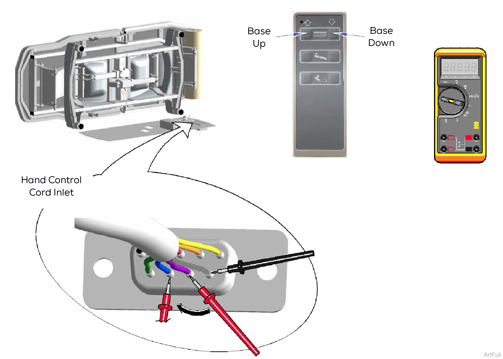
1.Remove bottom cover. Remove power inlet housing cover.
2.Set meter to read DC voltage.
When specified hand control button is pressed, does voltage drop to approximately 0.7 VDC? If Yes, replace control box. If No, replace hand control.
3.Place black probe on Grey wire (common).
4.Place red probe on Black wire. Press Tilt Down button on hand control. Check meter as button is pressed and released.
5.Move red probe to Green wire. Press Tilt Up button on hand control. Check meter as button is pressed and released.
