244 Table Back Actuator Test and Repair
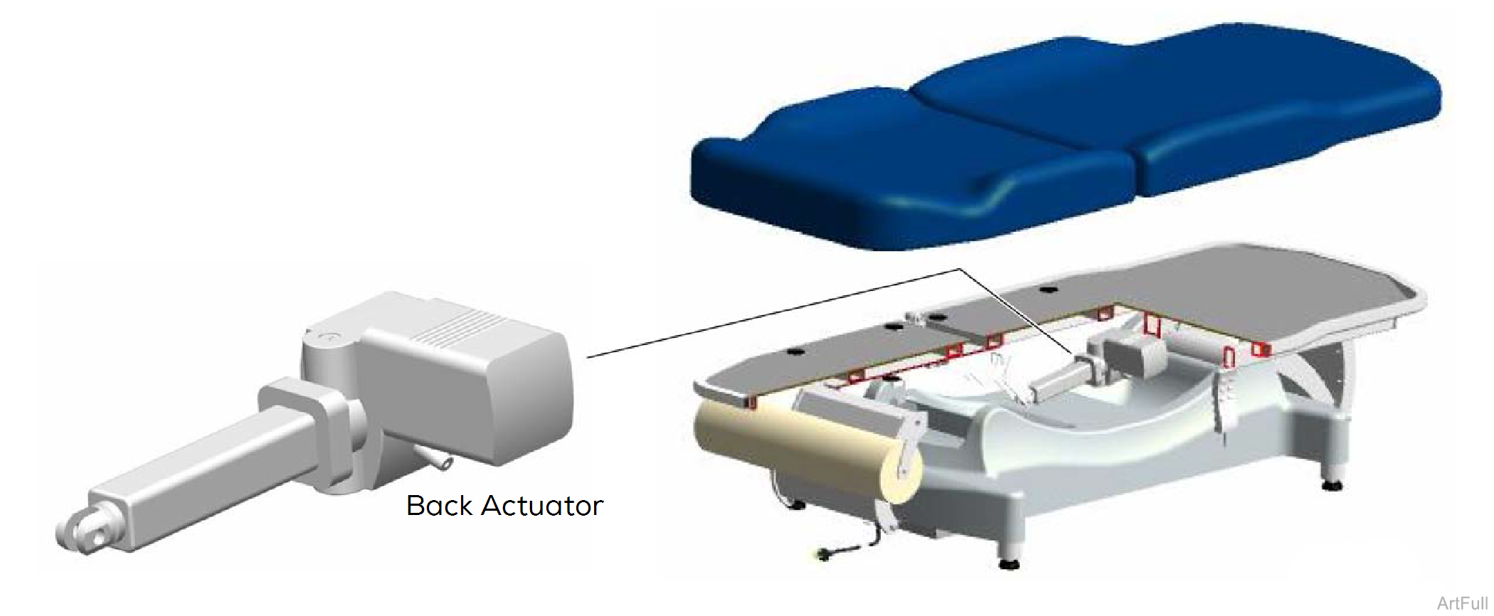
Under normal operating conditions, the hand control continuously supplies 5 VDC to the control box thru separate wires for each table function. When a function is selected from the hand control, this "signal voltage" is removed from the wire corresponding to the selected function.
When the signal voltage is removed, the control box activates the selected function and supplies 24 VDC to the actuator.
Back actuator motor runs until
1.Hand control button is released.
2.Actuator reaches its max./min. limits. Internal limit switches are not serviceable.
| Function | Action |
|---|---|
| Back Up | Back actuator extend |
| Back Down | Back actuator retract |
This procedure may be performed with the table upright.
1.Disconnect power to table.
Early models do not have a removable channel cover. To access the electrical connector, remove the seat section cover. Refer to: Seat Section Cover
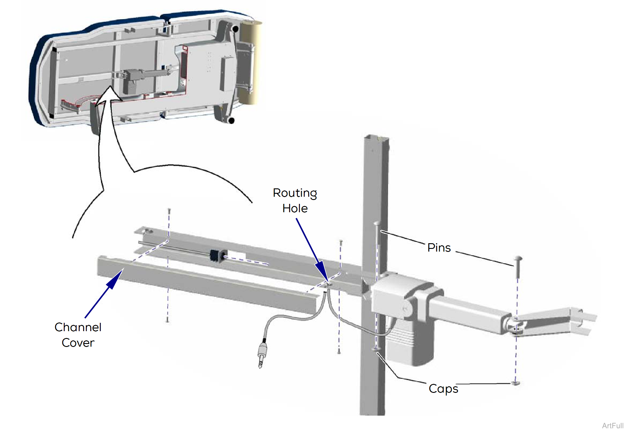
2.On models with removable channel cover, remove four screws and channel cover.
3.Disconnect back actuator wire from the electrical connector.
4.Pull actuator wire out thru routing hole.
5.Pry off two caps.
6.Remove two pins and actuator.
1.Position actuator.
2.Install two pins and caps.
3.Insert actuator wire thru routing hole.
4.Connect actuator wire to electrical connector.
5.Replace channel cover and secure w/ four screws.
1.Disconnect power to table.
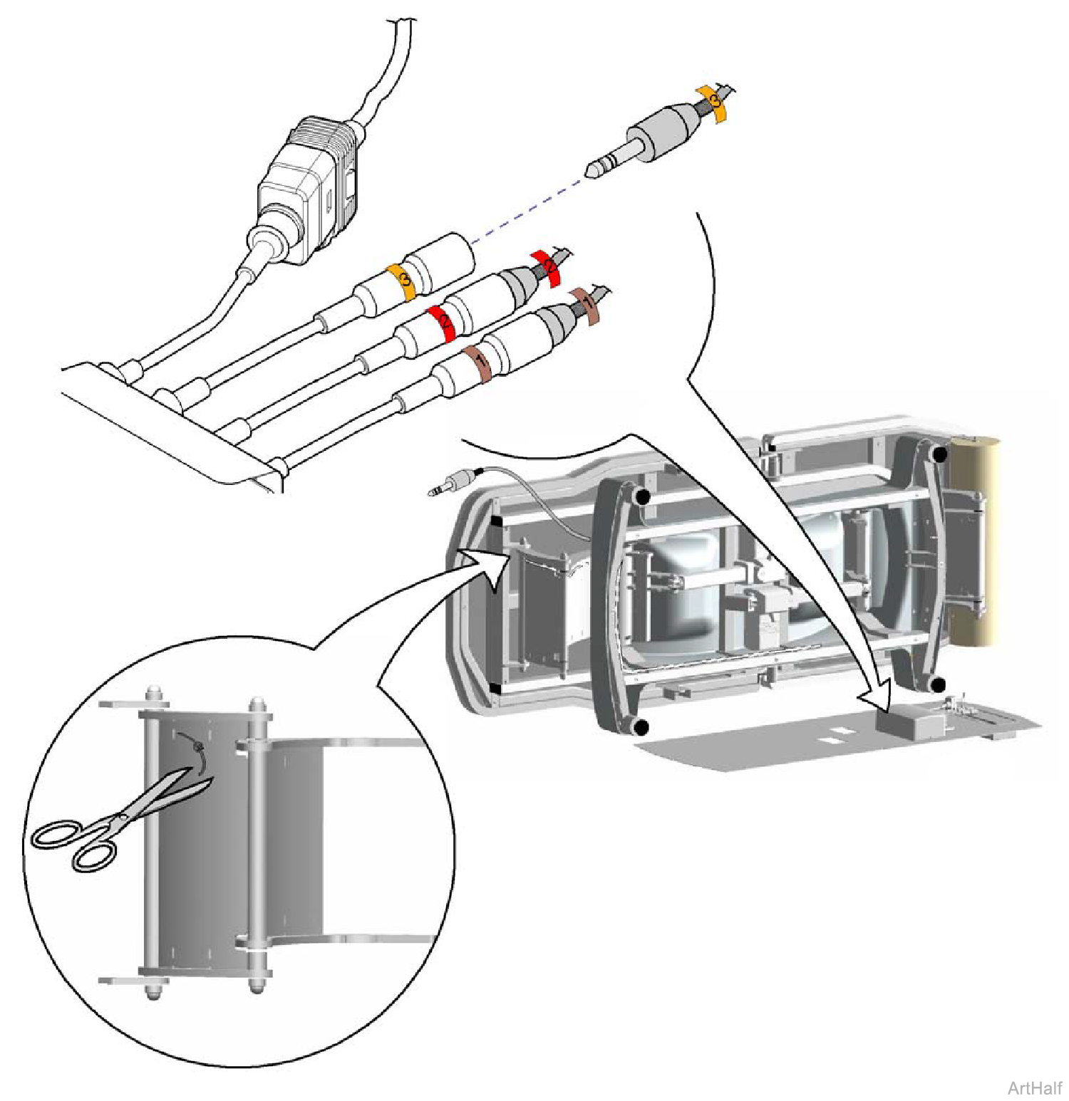
2.Remove bottom cover.
3.Disconnect wire harness extension (3) from control box wire (3).
4.Cut all wire ties securing the wire harness extension. Pull harness extension up thru base cover.
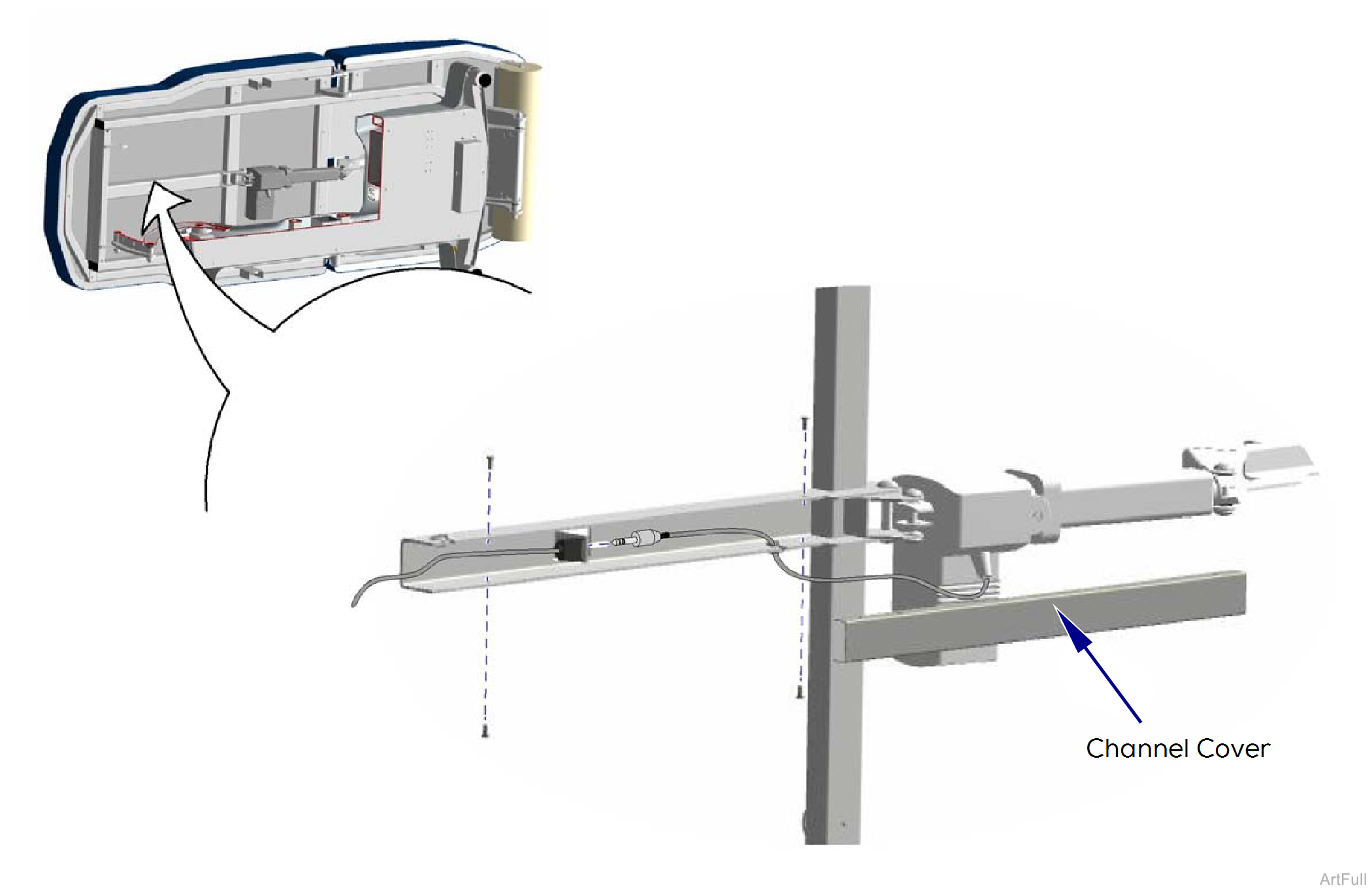
5.On models with removable channel cover, remove four screws and channel cover.
6.Disconnect back actuator wire from the electrical connector.
Early models do not have a removable channel cover. To access the electrical connector, remove the seat section cover. Refer to: Seat Section Cover
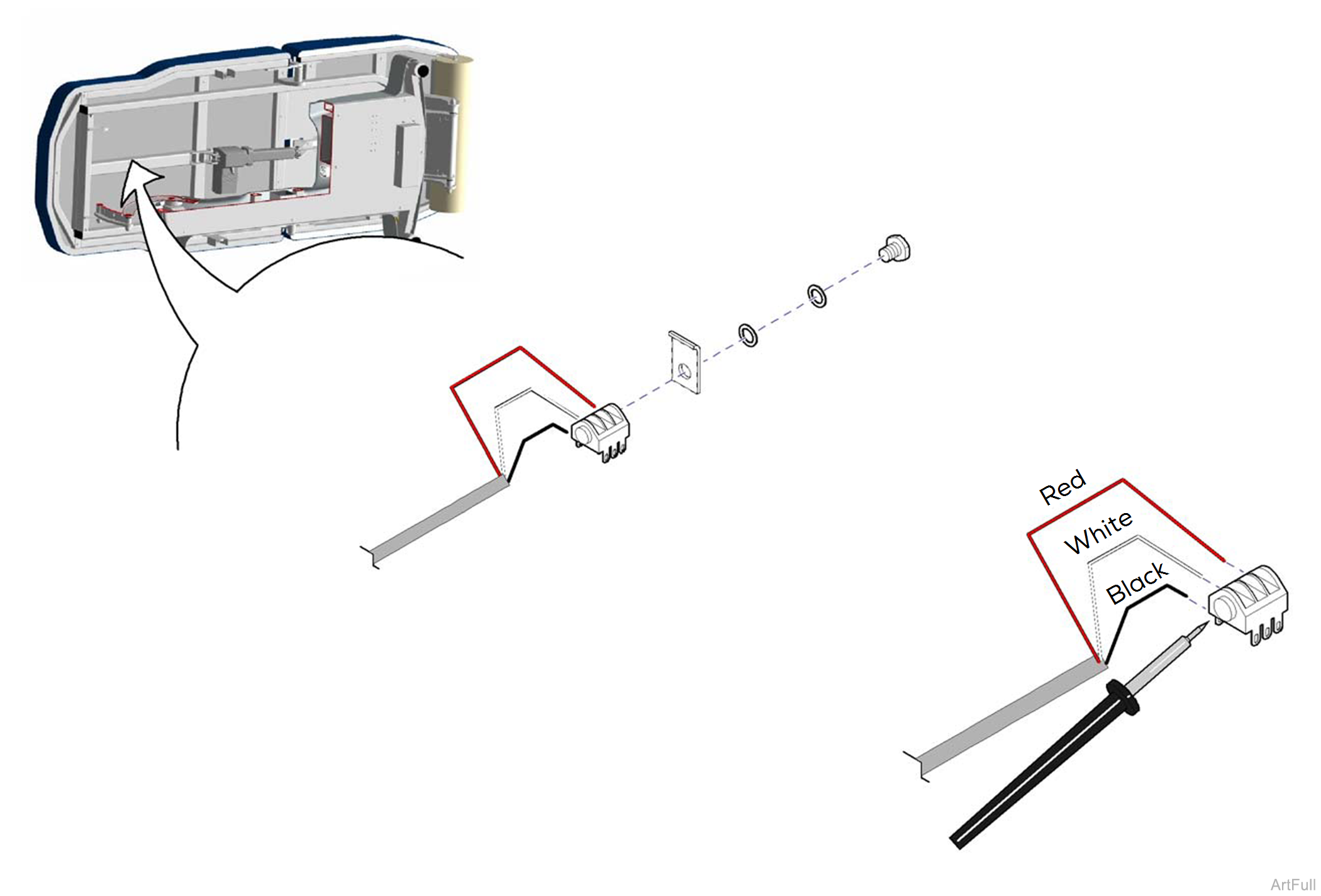
7.Remove nut, two washers, and electrical connector / wire harness extension.
1.Connect wire harness extension (3) to control box wire (3).
2.Route wire harness extension up to the electrical connector channel. Replace all wire ties cut during removal procedure.
3.Solder three harness extension wires to the proper terminals of the electrical connector.
4.Position electrical connector, then secure with two washers and nut.
5.Connect back actuator wire to electrical connector.
6.Install channel cover.
