641 Chair Position Sensors Test and Repair
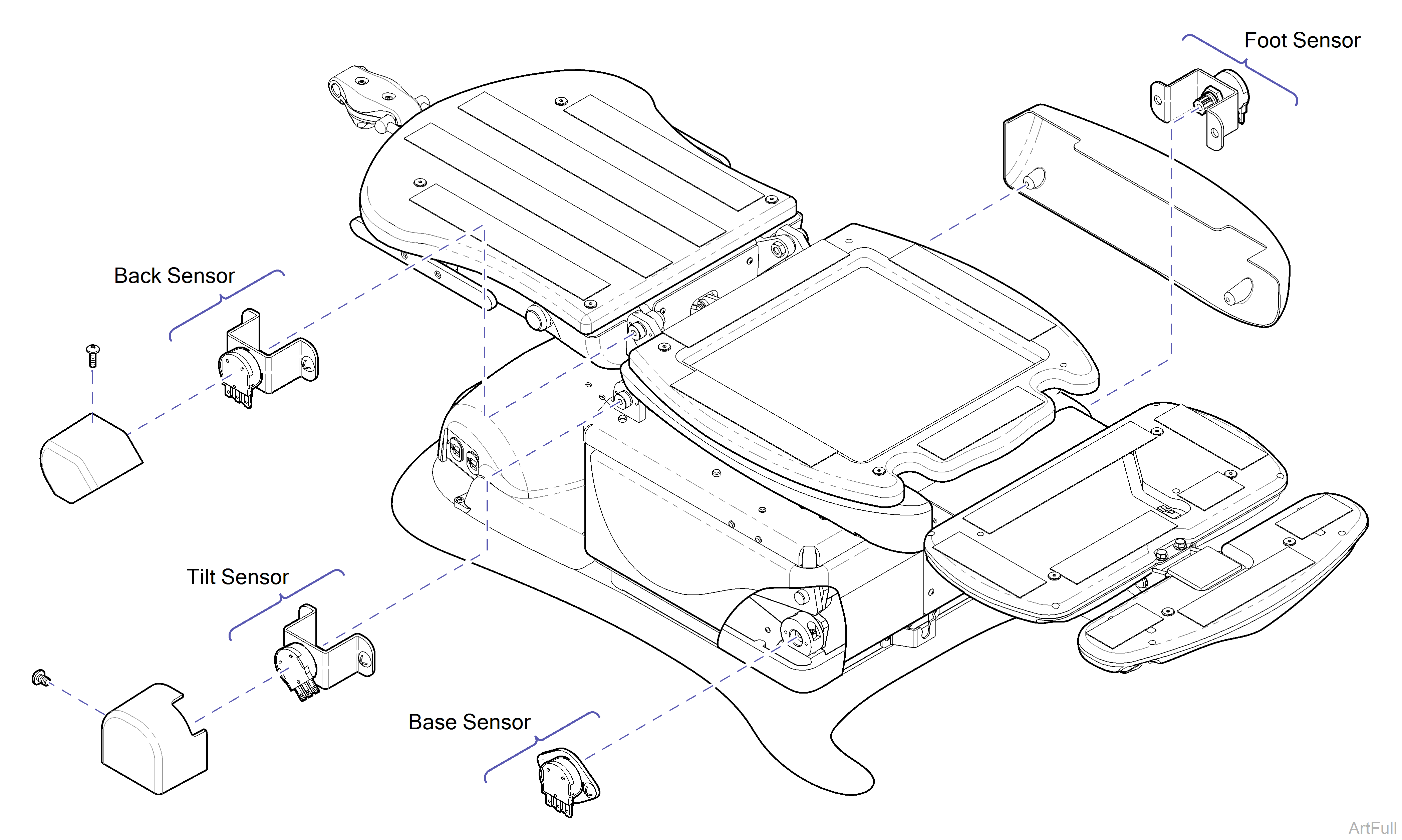
1.Verify position sensor shoulder bolts are tight (50 ft-lbs). This step does not apply to the Base position sensor.
2.Perform Output Voltage Test at Sensor.
This test must always be performed first. The results from this test determine the next required action.
| Affected Sensor | Affected Functions |
|---|---|
| Back Sensor |
Back Up / Down Crash Avoidance System Position Programming |
| Foot Sensor |
Foot Up / Down Crash Avoidance System Position Programming |
| Tilt Sensor |
Tilt Up / Down Crash Avoidance System Position Programming |
| Base Sensor |
Base Up / Down Crash Avoidance System Position Programming "Home" Function |
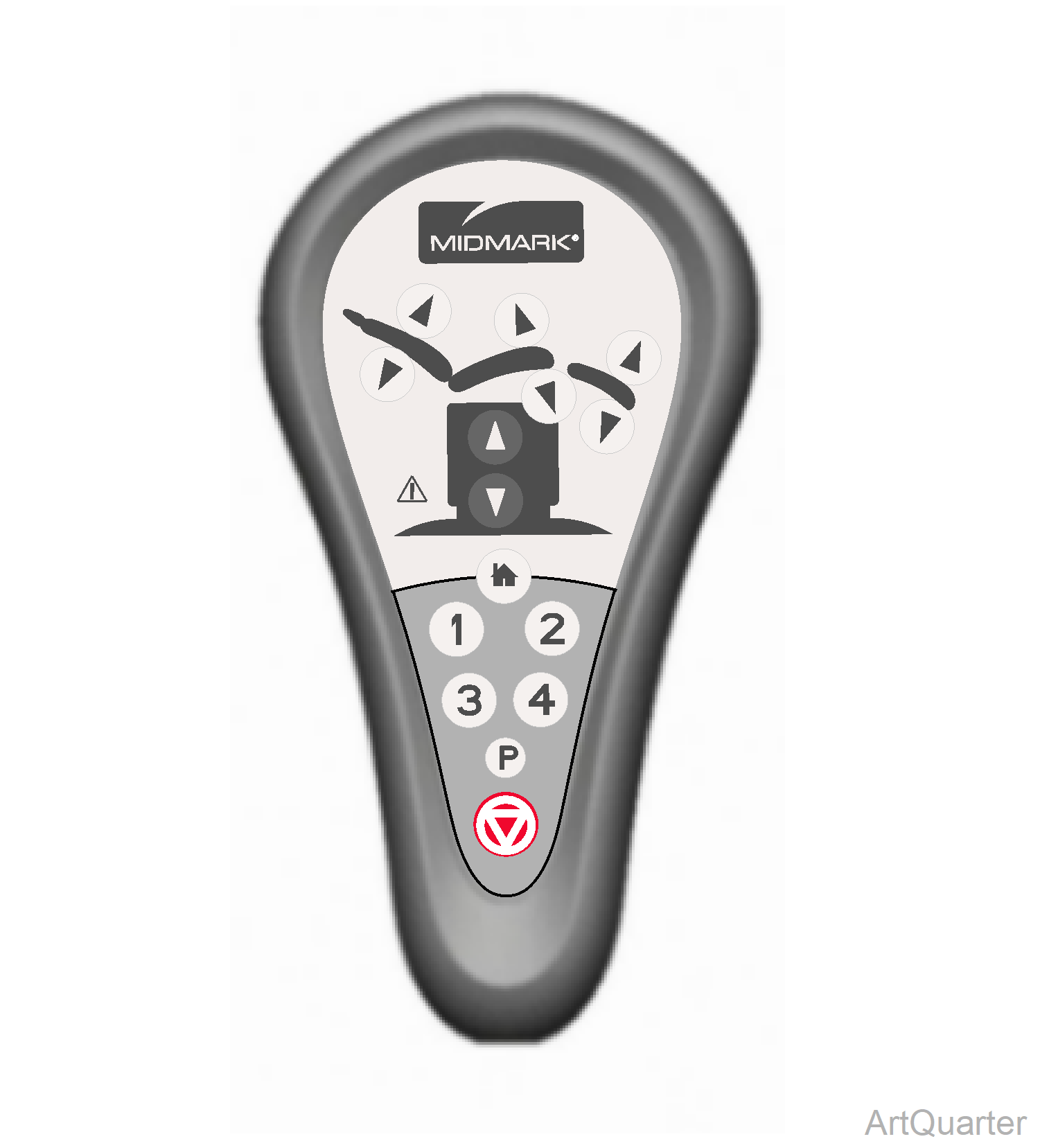
If Tilt is stuck in the Down position
1.Disconnect the White and Black wires at J7 and J8 on Main PC Board.
2.Connect Black wire to J7 and White wire to J8.
3.Perform Output Voltage Test on Tilt Up function by pressing the Tilt Down button.
Do not run Tilt Up function beyond the halfway position.
4.Reconnect White wire to J7 and Black wire to J8. Perform Output Voltage Test on the Tilt Down function.
Output Voltage Test
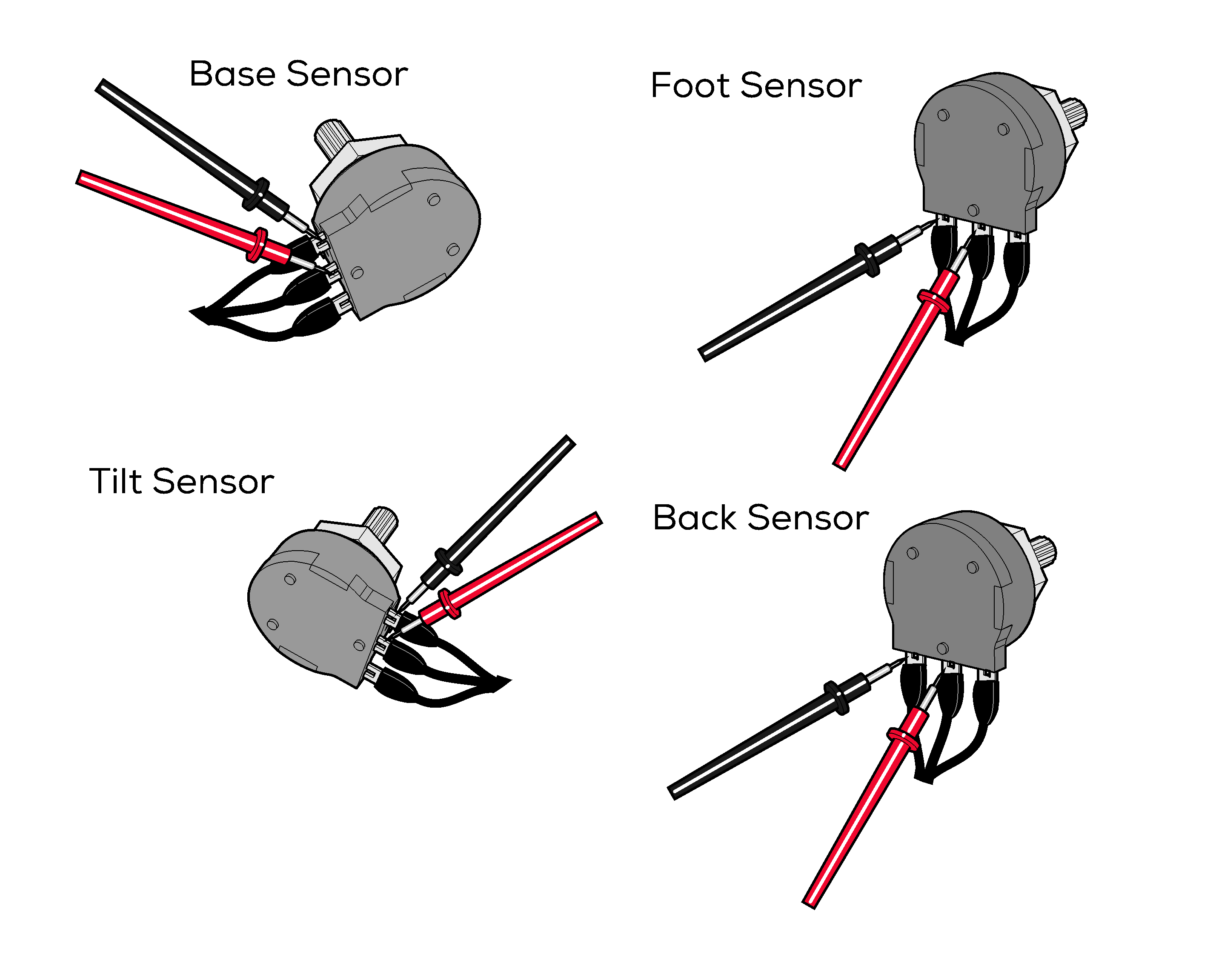
1.Set meter to 20 VDC. Place meter probes on proper terminals. See illustration.
2.Run desired function up and down. Watch meter reading as function moves.
Each sensor has a different voltage range.
| Meter Reading | Sensor Status | Required Action |
|---|---|---|
|
Voltage steadily increases / decreases as function moves up / down |
|
Perform Output Voltage Test at PC Board. |
|
Voltage does not change, or changes erratically as function moves up / down |
|
Perform Supply Voltage Test at Sensor. |
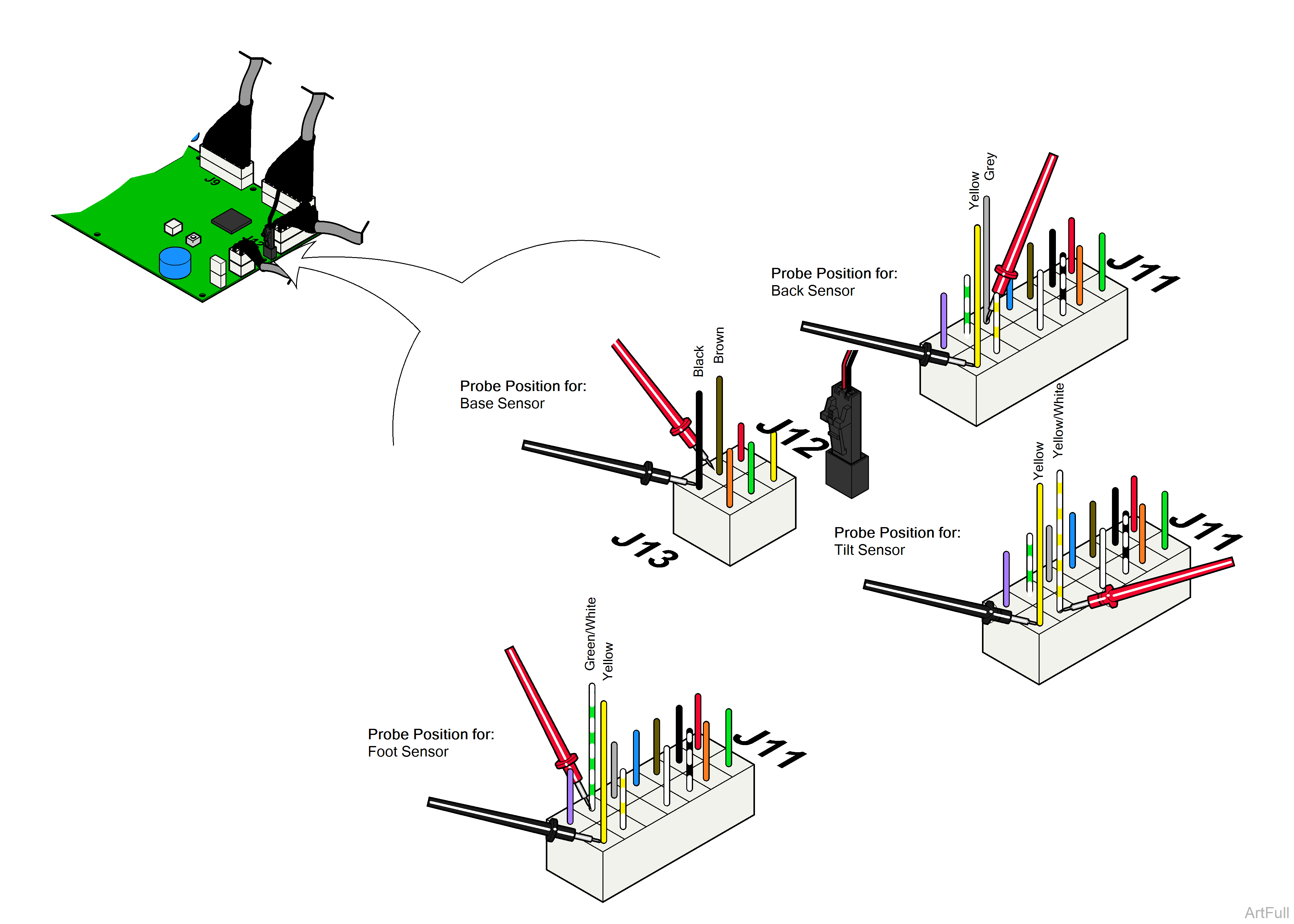
1.Set meter to VDC.
2.Place meter probes on proper wires. See illustration.
3.Run desired function up and down. Watch meter reading as function moves.
Each sensor has a different voltage range.
| Meter Reading | PC Board Status | Required Action |
|---|---|---|
|
Voltage does not change, or changes erratically as function moves up / down |
|
Check wire harness (connections, damage, etc) |
|
Voltage steadily increases / decreases as function moves up / down |
|
Replace PC Board*. |
*Before replacing PC board, be sure shoulder bolt at the position sensor pivot point is tight. If bolt is loose, tighten it, then recalibrate PC board and check for proper operation.
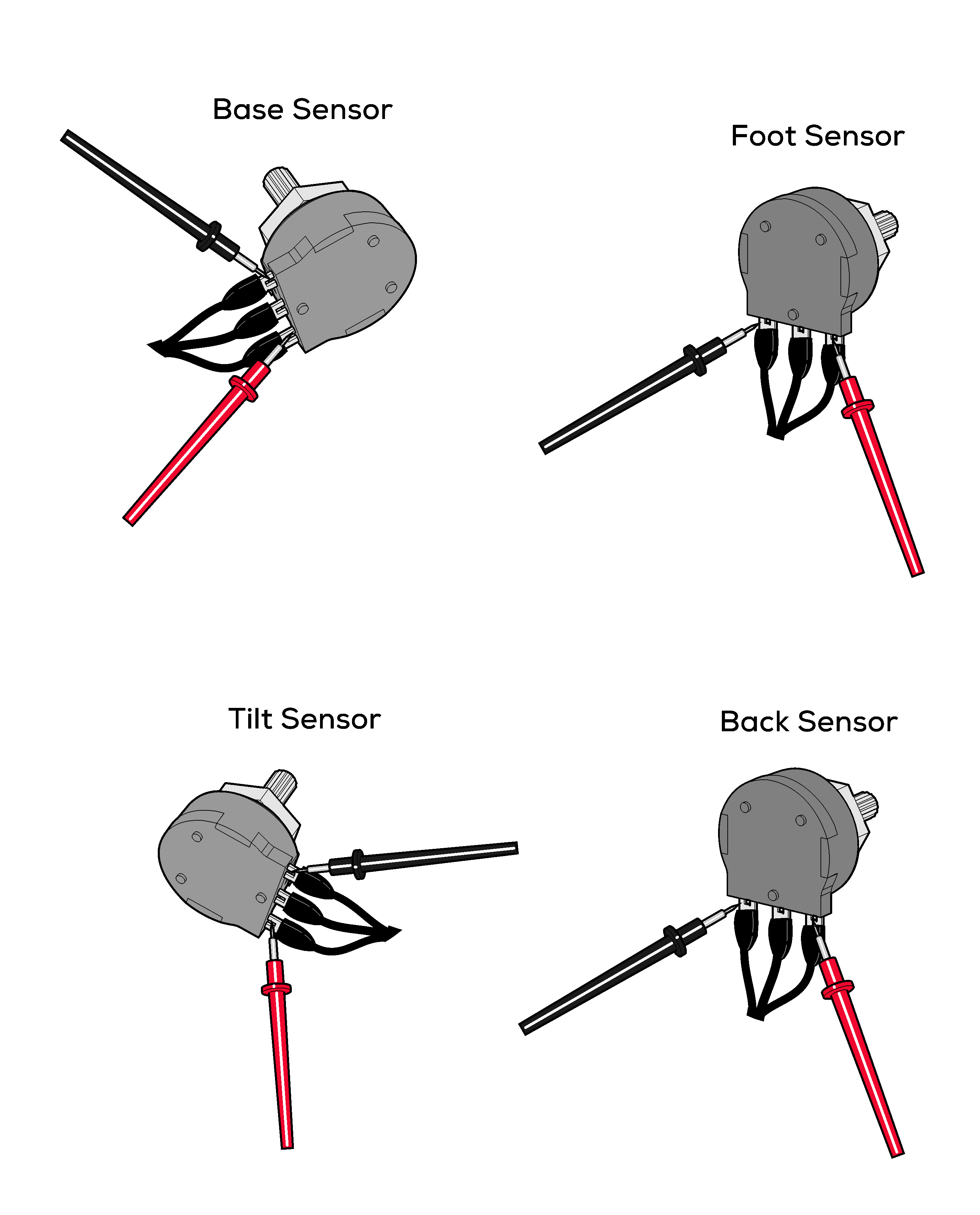
1.Set meter to 20 VDC.
2.Place meter probes on proper terminals. See illustration. Check meter reading.
3.With meter probes in same position, run Base function to max / min. position. Check reading as function moves.
| Meter Reading | Sensor Status | Required Action |
|---|---|---|
|
2 to 4 VDC |
|
Position Sensor Adjustment. Replace position sensor*. |
|
less than 2 VDC, more than 4 VDC |
|
Perform Supply Voltage Test at PC Board. |
|
Reading changes erratically as Base moves up / down |
|
Perform Supply Voltage Test at PC Board. |
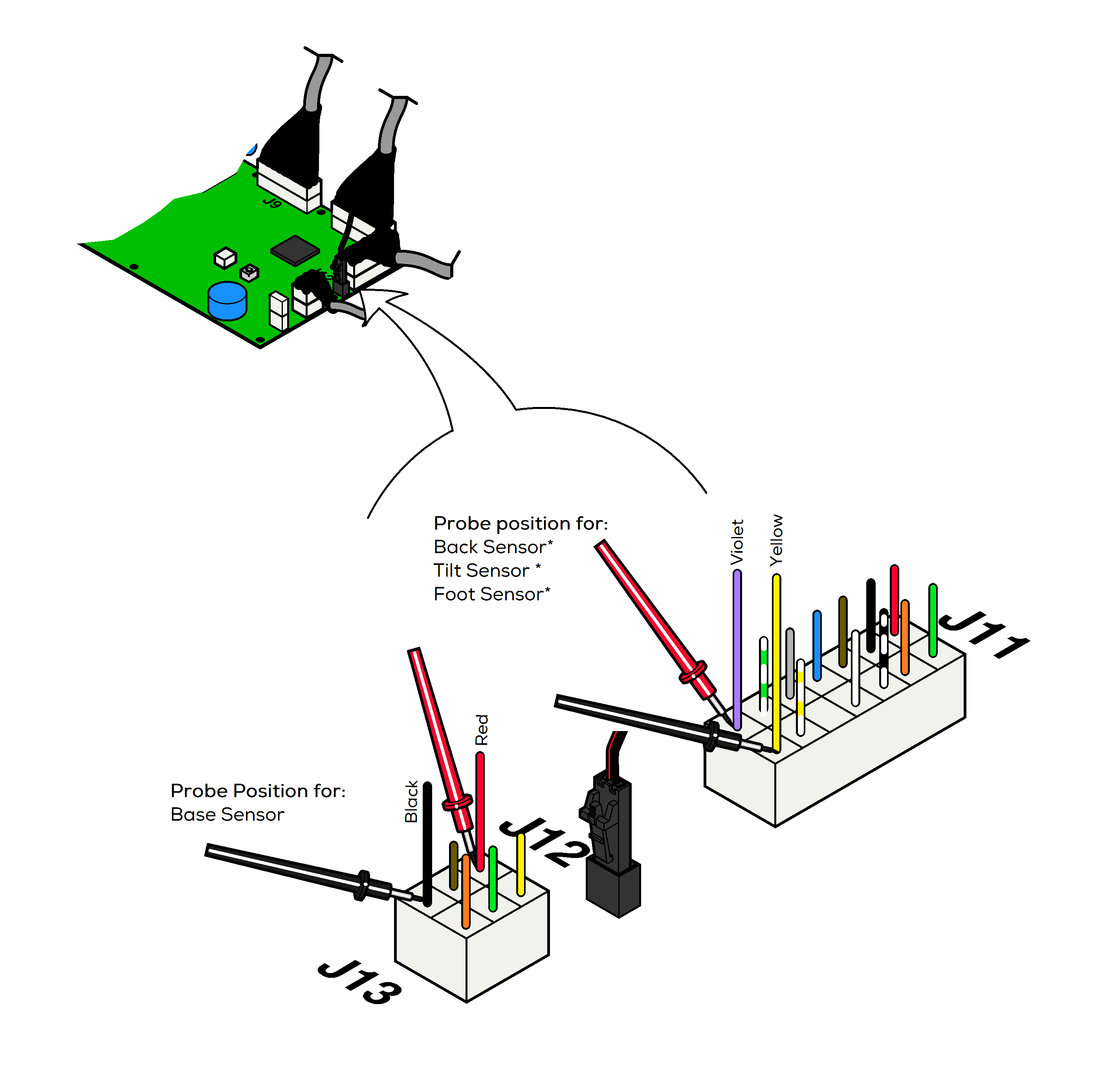
1.Set meter to 20 VDC.
2.Place meter probes on proper wires. See illustration.
* Back / Tilt / Foot only - If initial reading is less than 2 VDC or more than 4 VDC, unplug J11 connector and check meter reading at pins on PC board at the same location.
| Meter Reading | PC Board Status | Required Action |
|---|---|---|
|
2 to 4 VDC |

|
Replace sensor wire harness between sensor and junction board or junction board and PC board. |
|
< 2 VDC |

|
Replace PC board. |
|
> 4 VDC |

|
Replace PC board |
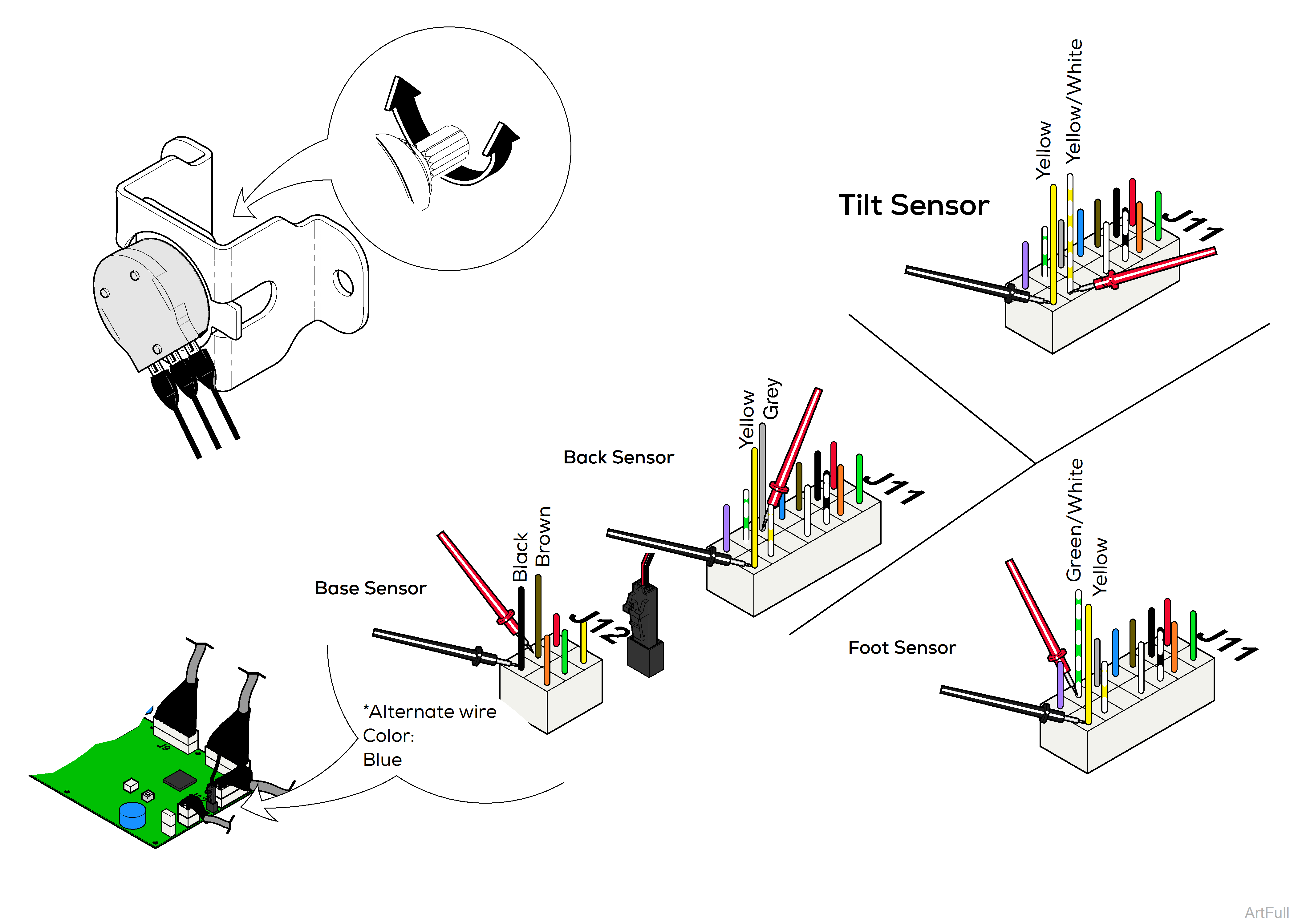
1.Remove main PC board cover. Place meter probes as shown to test desired sensor.
2.Position Base / Back / Foot functions all the way Up and the Tilt function all the way Down. Turn sensor knob until voltage matches the chart below.
3.Perform PC Board Calibration.
| Sensor Function Position | Voltage Reading |
|---|---|
|
Base all the way Up |
1.7 to 2.1 VDC |
|
Back all the way Up |
2.4 to 2.6 VDC |
|
Tilt all the way Down |
1.8 to 2.1 VDC |
|
Foot all the way Up |
2.4 to 2.6 VDC |


