PowerVac G Contactor Test and Repair
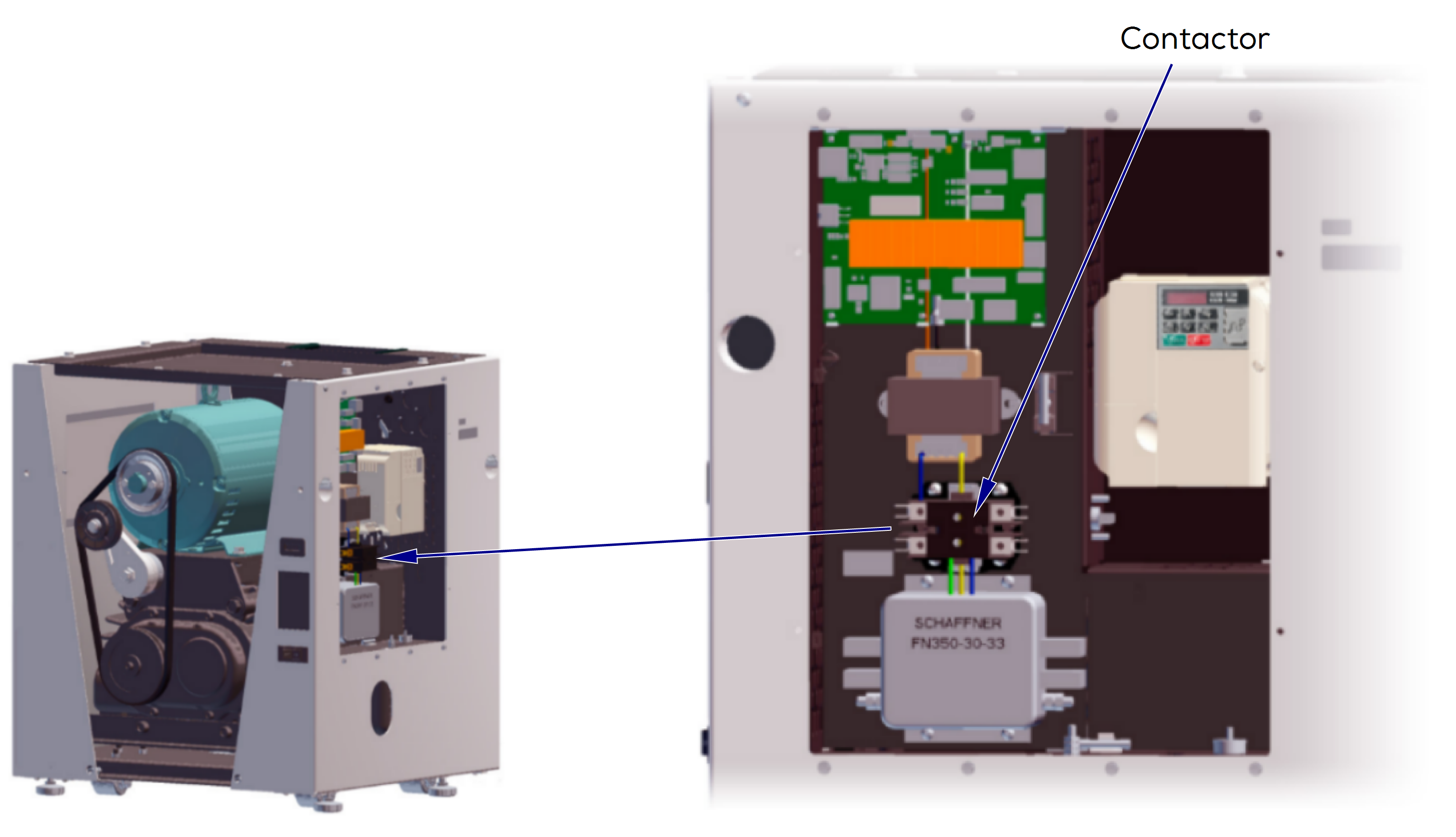
When the contactor is energized, it closes and connects the Main input power supply to the line filter. Main input power supply is then applied to the Variable Frequency Drive (VFD) through R/L1 and S/R2 (single phase).
1.Turn power off at on/off switch and main power supply box.
2.Remove electrical cover. Refer to: Electrical Cover
3.Turn power on. Set meter to V. Check voltage on PC board at J5 connection. Also verify black plastic “shunt” is on J16. Refer to: PC board. Verify reading is 24 VAC.
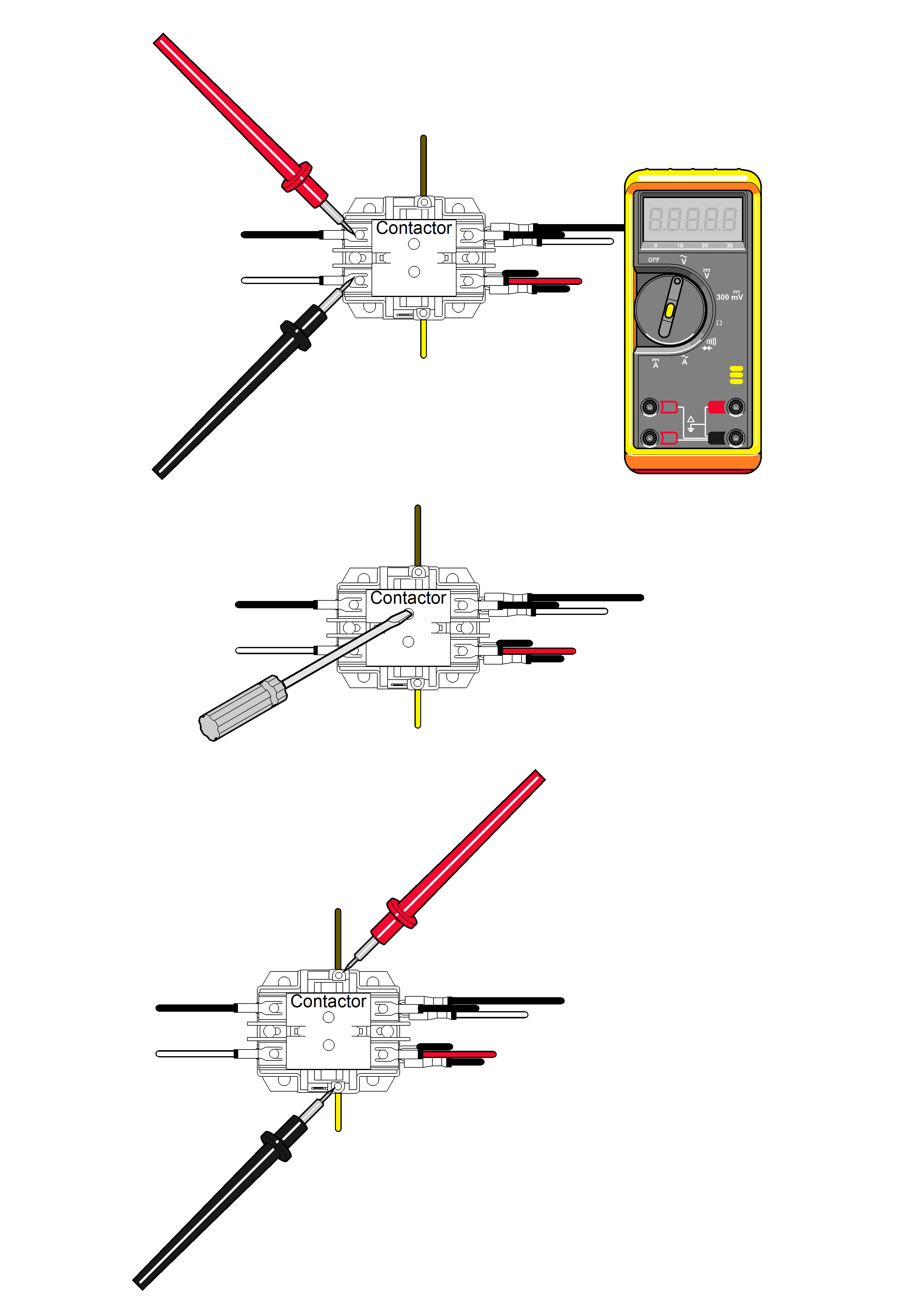
4.Check high voltage on contactor.
5.Set meter to V. Place meter probes on front, left side white and black wires. Verify reading is 207-253 volts.
6.Check voltage across contactor.
7.Set meter to V. Place meter probes on top brown wire and bottom yellow wire. Verify reading is 24 volts.
8.Insert screwdriver to start manually. If system starts, replace contactor.
9.Install electrical cover.
| Meter Reading | Required Action |
|---|---|
| 24 Volts - PC Board Check | Contactor OK |
| 207-253 Volts - Left Side Check | Contactor OK |
| 24 Volts - Top and Bottom Check | Contactor OK |
