626 Chair Base Function Test and Repair
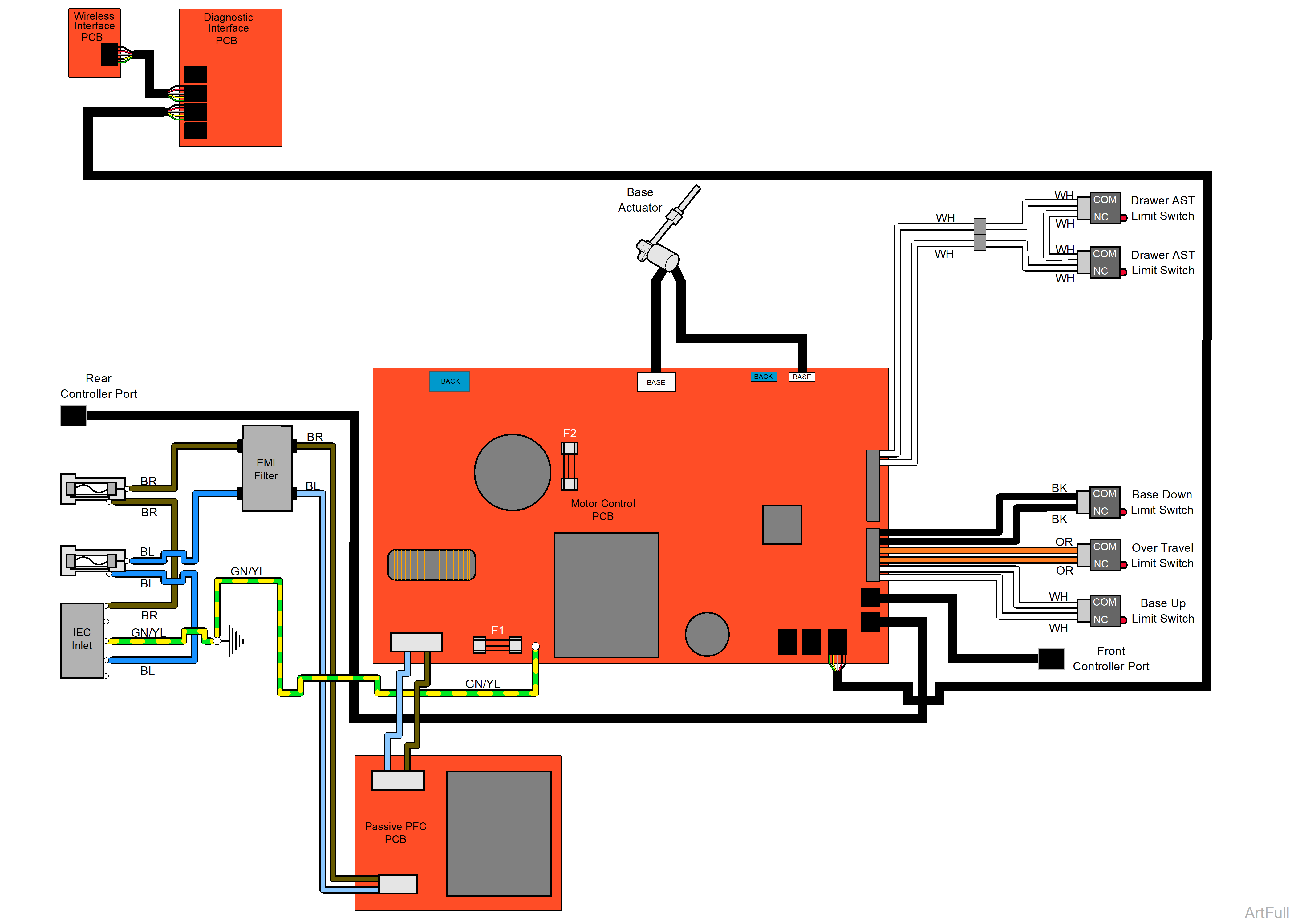
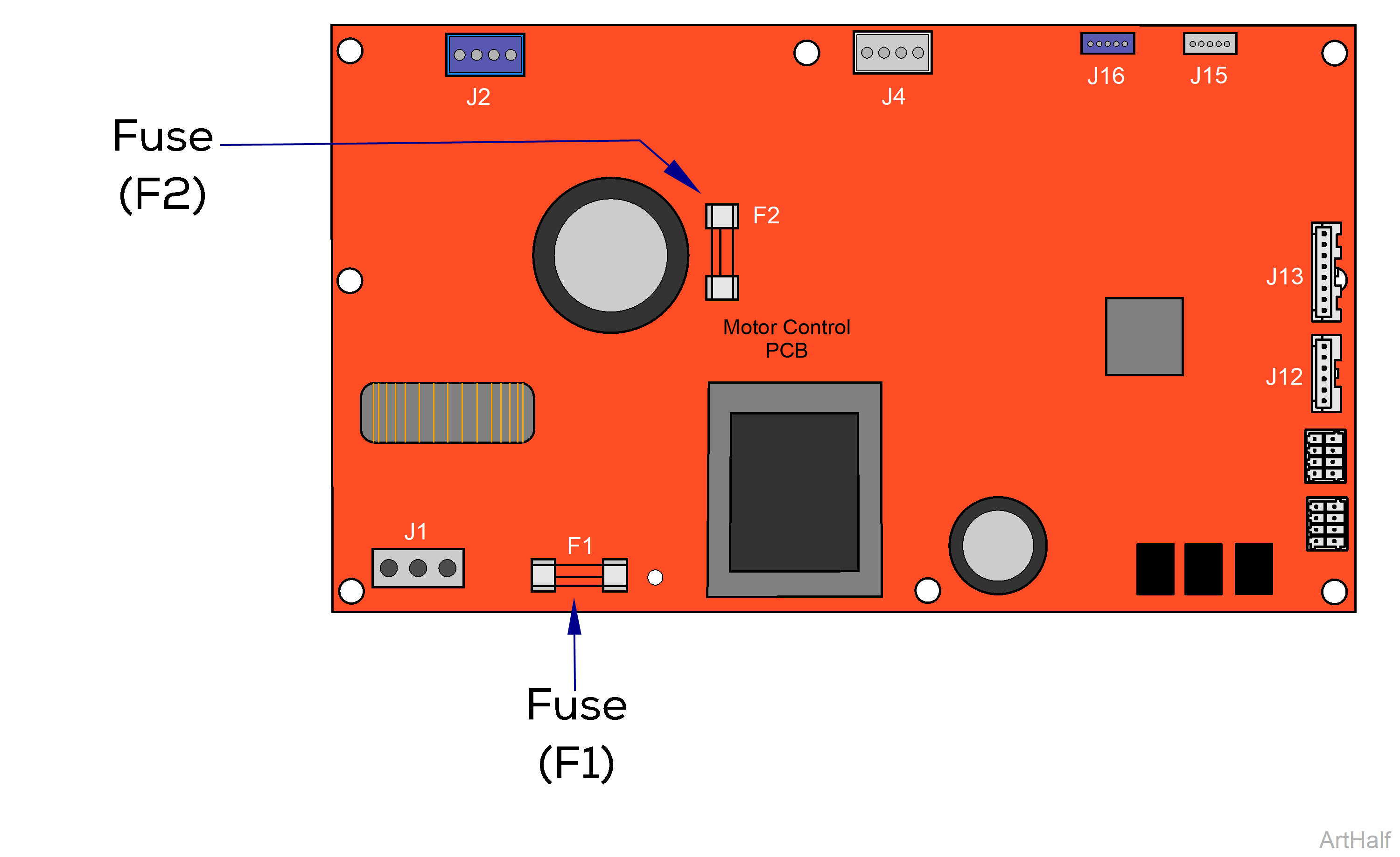
This illustration shows only the fuses and connections that affect the Base Up / Down function.
This illustration shows only the fuses and connections that affect the Base Up / Down function.
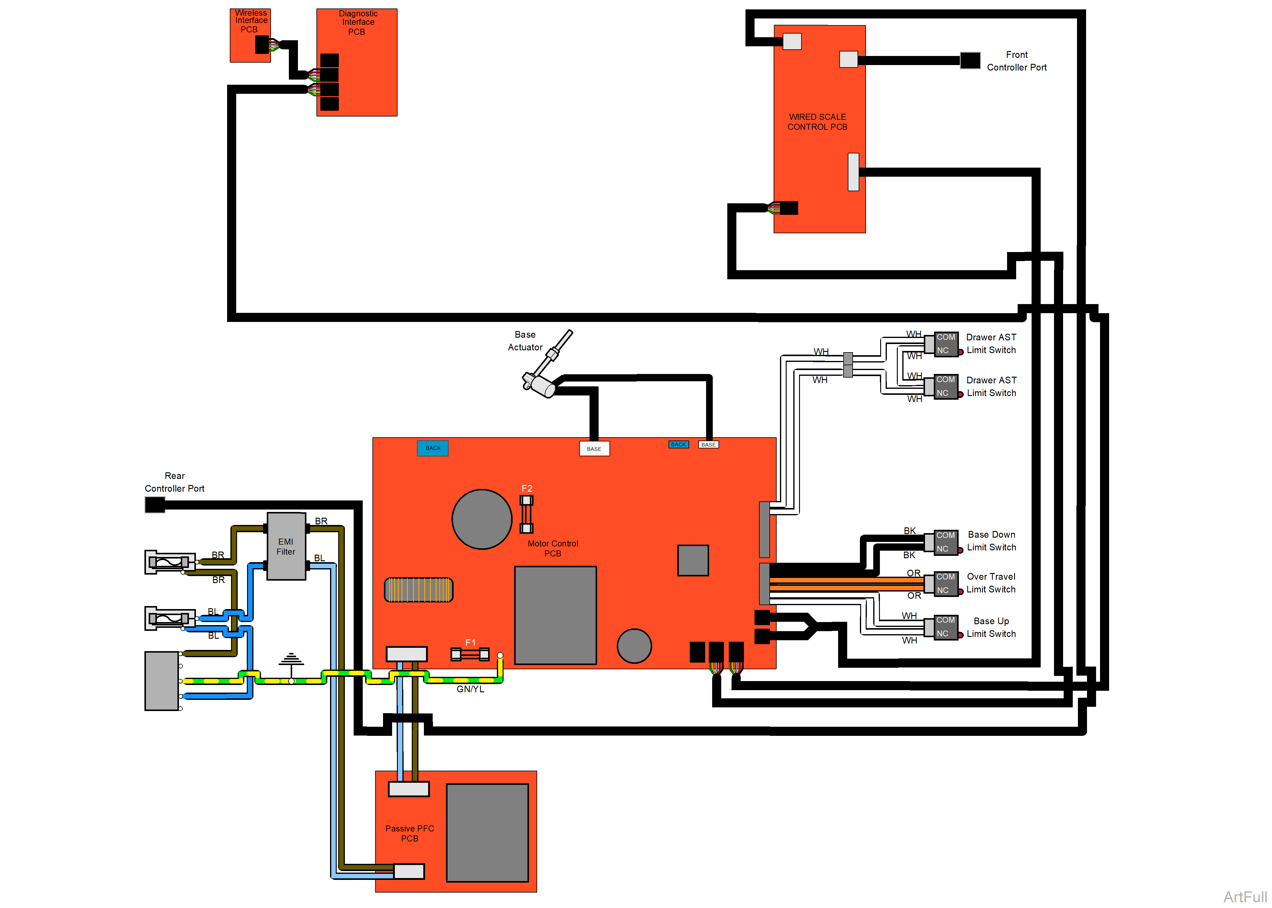
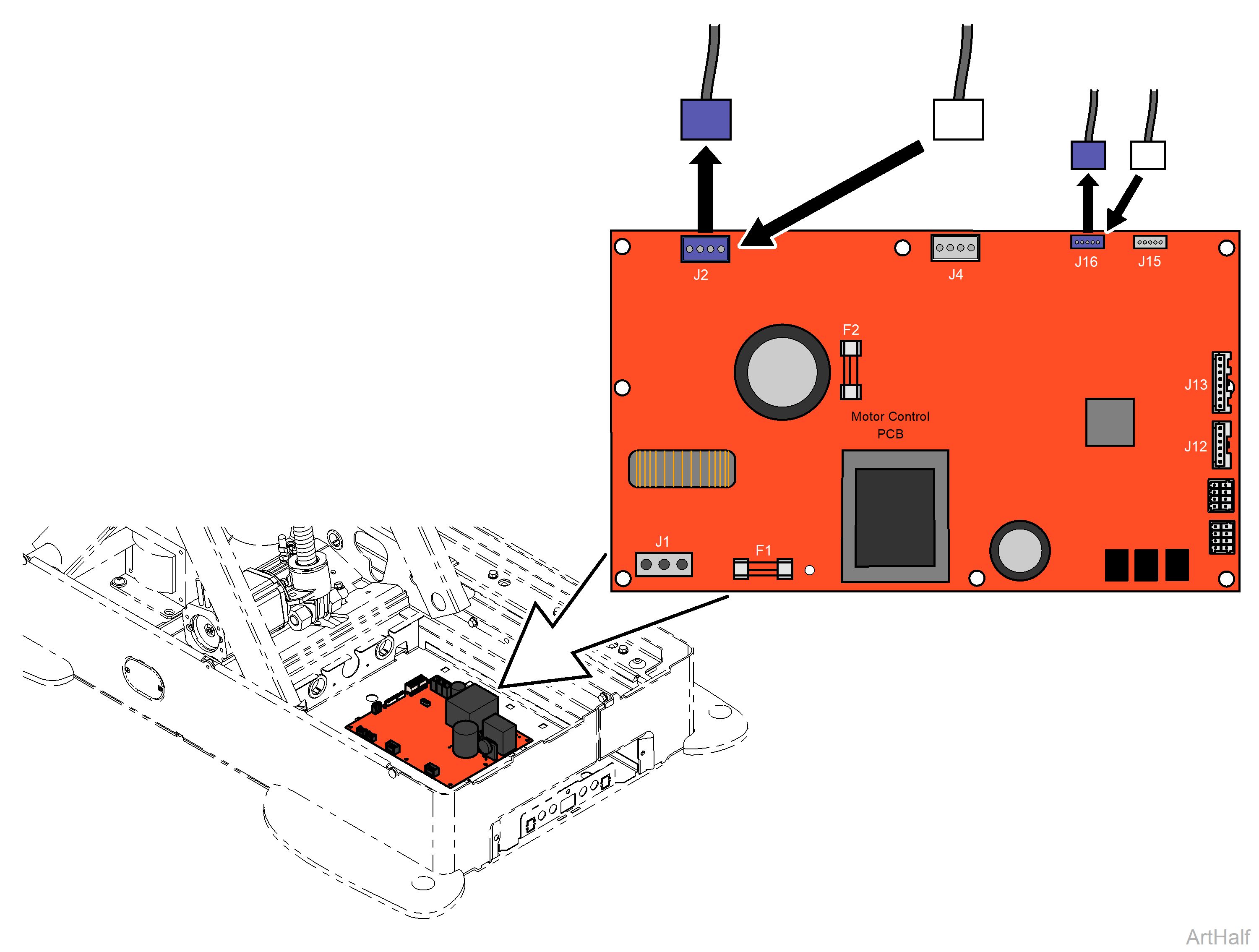
This illustration shows the fuses and connections that affect the Base Up / Down and Back Up / Down functions.
This illustration shows the fuses and connections that affect the Base Up / Down and Back Up / Down functions.
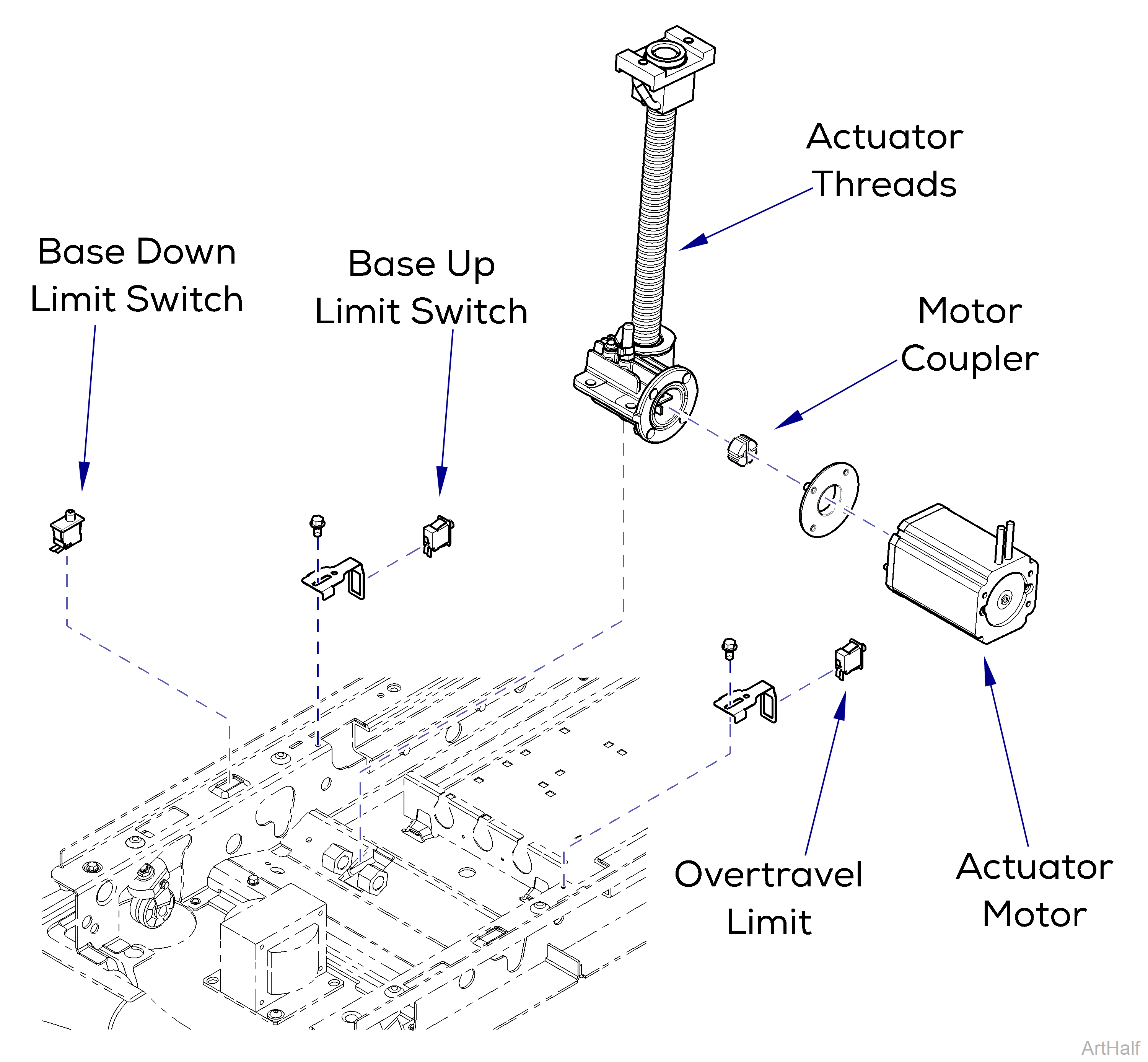
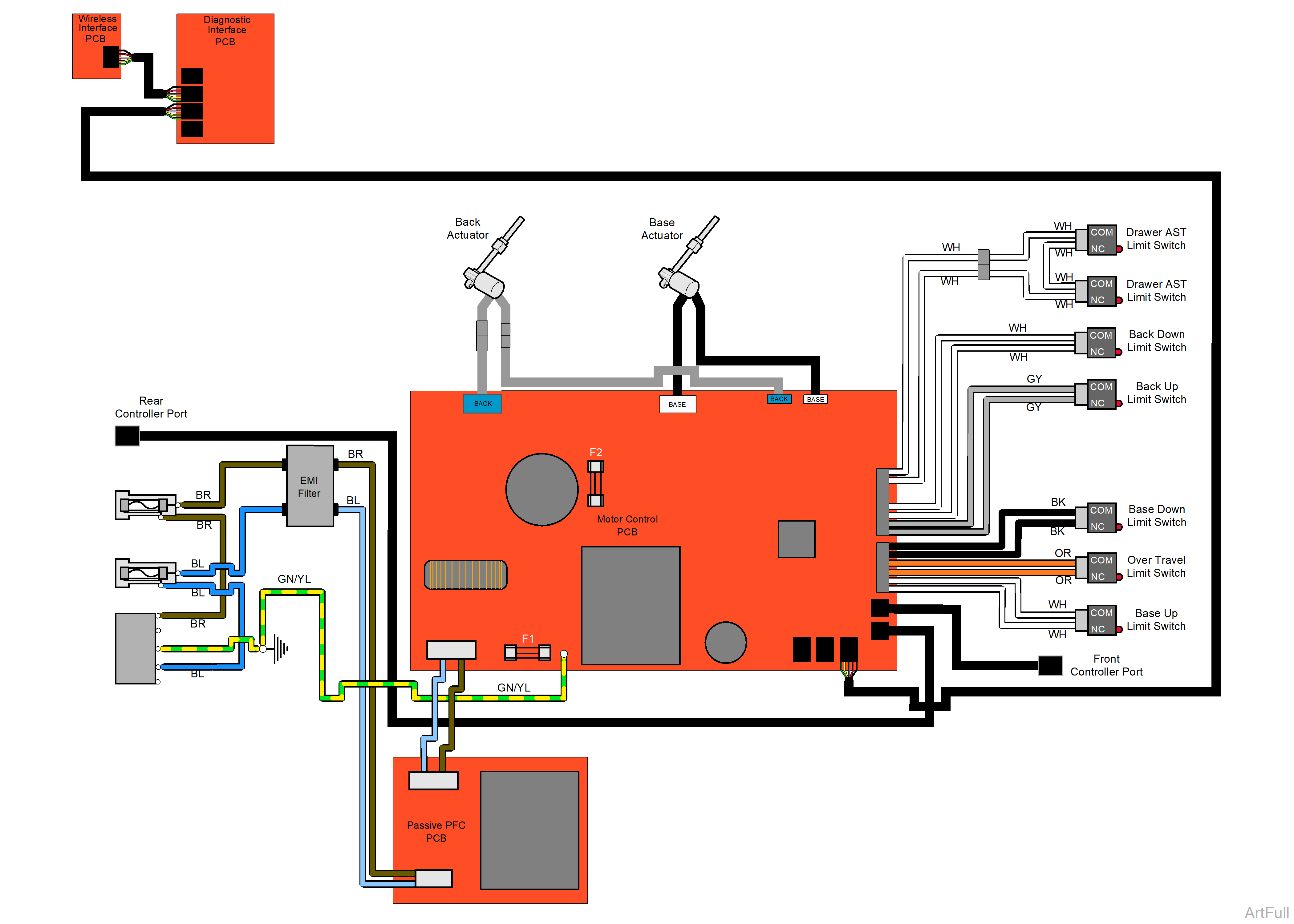
This illustration shows the Base limit switches, the serviceable components of the Base actuator, and the fuses on the Motor Control PC board.
Risk of electrical shock. Always disconnect chair power for three minutes, allowing capacitance to dissipate prior to servicing the Motor Control PC board.
Anytime an Overtravel Limit Switch is detected open, all functions are deactivated. Chair will continuously beep until powered down.
Use this table to isolate a malfunction.
|
Problem |
Required Action |
|---|---|
|
Motor runs, but makes grinding noise. |
Clean / lube actuator threads. Remove any debris from base slides. Do not lubricate base slides. Replace actuator if necessary. |
|
Motor runs, but chair does not move. |
Inspect / replace motor coupler. |
|
Motor does not run. |
Check Motor Control PC board fuses F1 and F2. |
| Perform Limit Switch Diagnostic Test | |
|
Check limit switch wire connections. |
|
|
Test Limit Switch(es). |
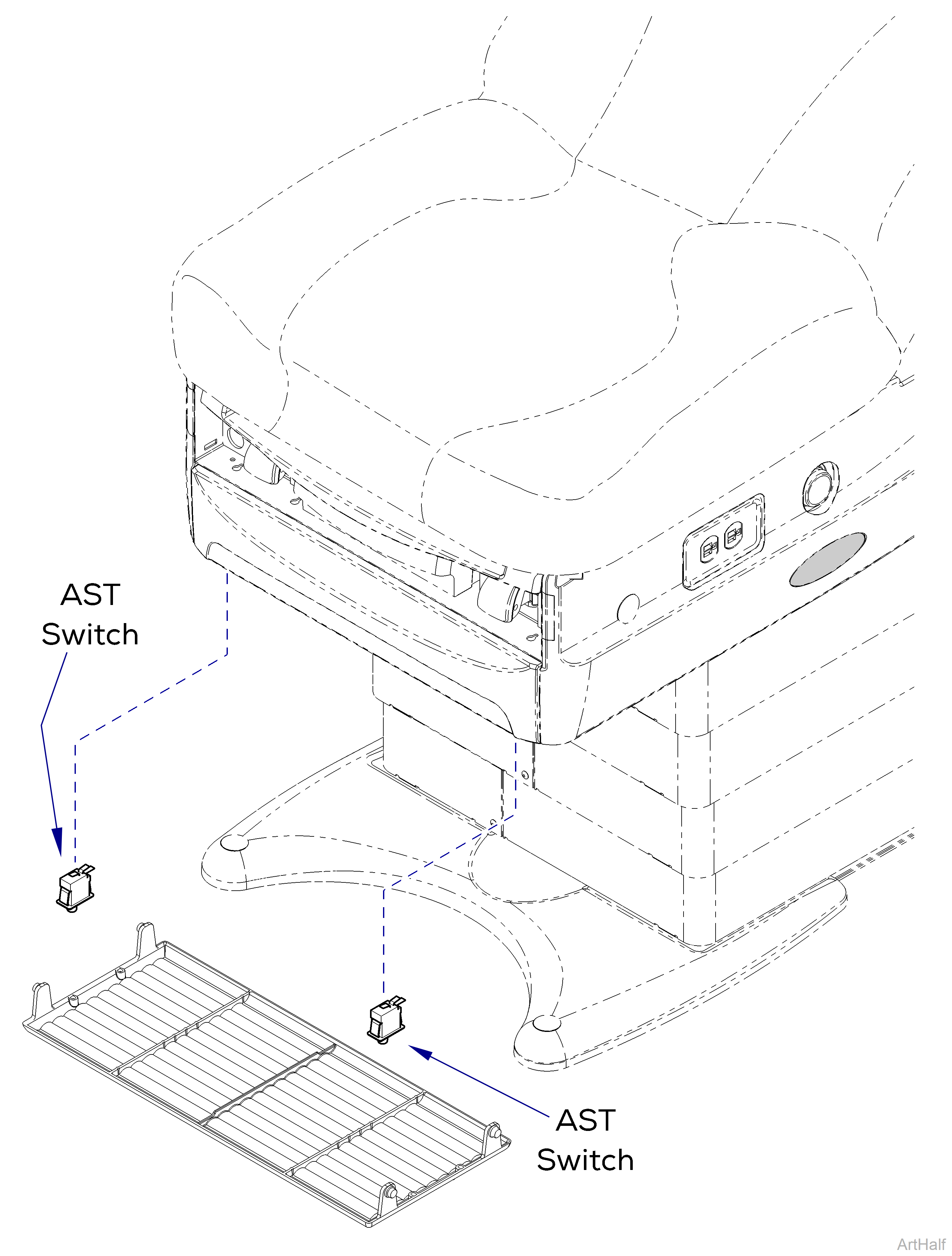
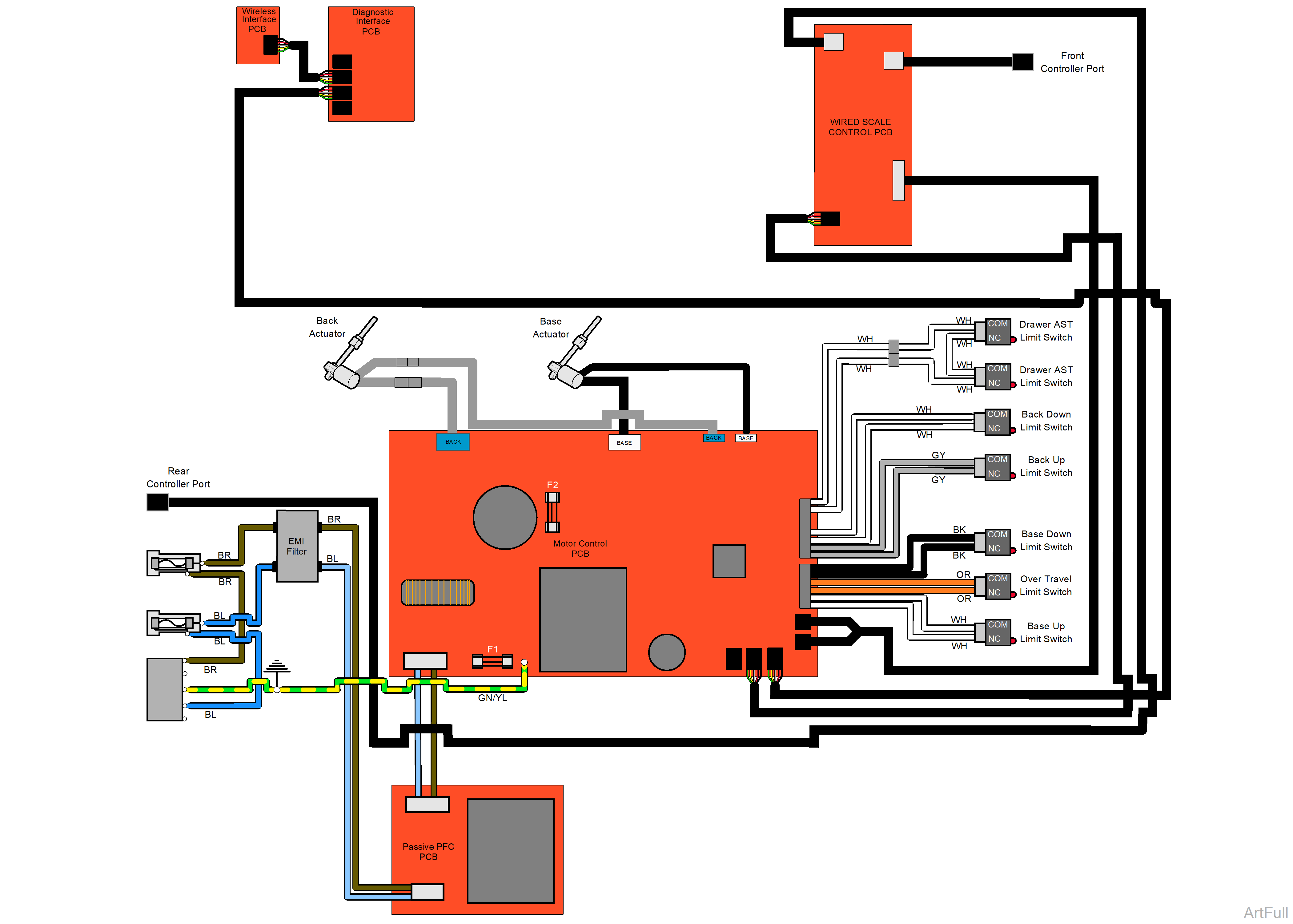
This illustration shows the Active Sensing Technology (ATS) switches and their location.
|
Problem |
Required Action |
|---|---|
| No Base Up/Down. Chair Beeps. | Perform Limit Switch Diagnostic Test |
| Check ATS switch wire connections. | |
| Test ATS switch(es). |
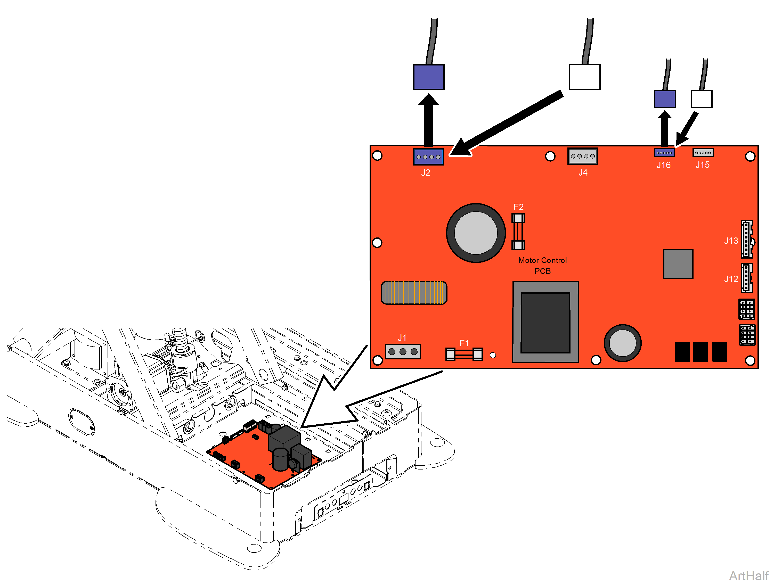
Risk of electrical shock. Always disconnect chair power for three minutes, allowing capacitance to dissipate prior to servicing the Motor Control PC board.
Do not to move chair past limit switches or equipment could be damage.
1.Disconnect power to the chair.
2.Disconnect Back actuator connections J2 and J16.
3.Move Base wire connection J4 to Back PC Board connection J2.
4.Move Base wire connection J15 to Back PC Board connection J16.
5.Connect power to chair.
6.Using the hand / foot control, press and hold Back Up button briefly.
7.Using the hand / foot control, press and hold Back Down button briefly.
|
Did Base Move Up and Down in Steps 6 and 7 |
Required Action |
|---|---|
|
Yes |
Actuator is OK |
|
No |
Replace actuator |
8.Reconnect Base actuator connections.
9.Reconnect Back actuator connections.
10.Calibrate Chair. Refer to: Calibration Procedure
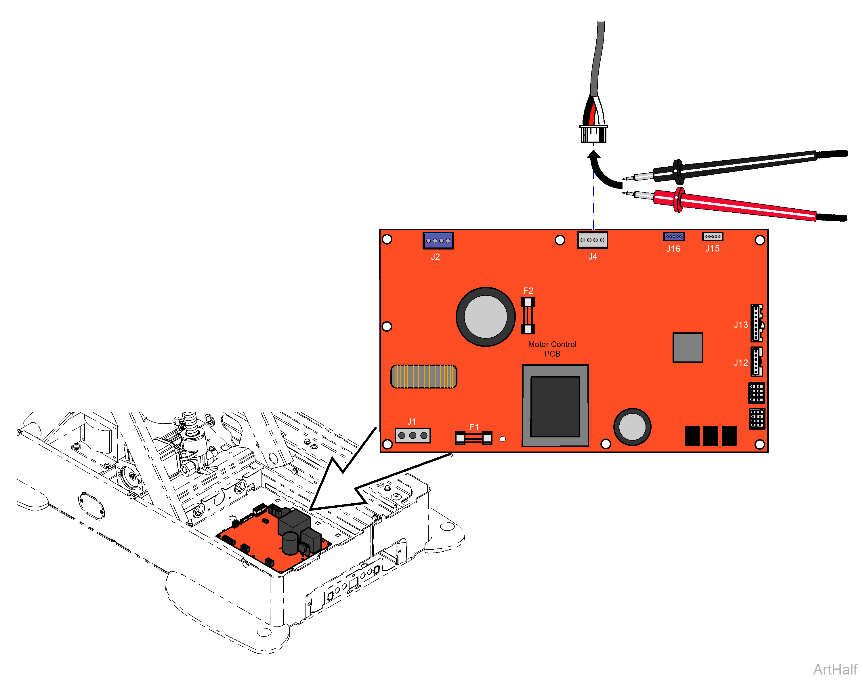
Risk of electrical shock. Always disconnect chair power for three minutes, allowing capacitance to dissipate prior to servicing the Motor Control PC board.
1.Disconnect power to the chair.
2.Disconnect Base actuator from J4 on PC Board.
3.Set multimeter to Ohms to check resistance.
4.Check resistance between the white and black wires.
5.Check resistance between the black and red wires.
6.Check resistance between the red and white wires.
|
Meter Reading |
Required Action |
|---|---|
|
1 - 20 Ohms |
Actuator motor is good. |
|
OL |
Replace actuator motor. |
Risk of electrical shock. Always disconnect chair power for three minutes, allowing capacitance to dissipate prior to servicing the Motor Control PC board.
Do not to move chair past limit switches or equipment could be damage.
1. Disconnect power to the chair.
2.Disconnect Back actuator connection J2 and J16.
3.Move Base wire connection J4 to Back PC Board connection J2.
4.Move Base wire connection J15 to Back PC Board connection J16.
5.Connect power to chair.
6.Using the hand / foot control, press and hold Back Up button briefly.
7.Using the hand / foot control, press and hold Back Down button briefly.
|
Did Base Move Up and Down in Steps 5 and 6 |
Required Action |
|---|---|
|
Yes |
Replace PC Board |
|
No |
Refer to: Base Function Components |
8.Reconnect Base actuator connections.
9.Reconnect Back actuator connections.
10.Calibrate Chair. Refer to: Calibration Procedure
