230 Universal Procedures Chair Foot Up / Down Function Troubleshooting
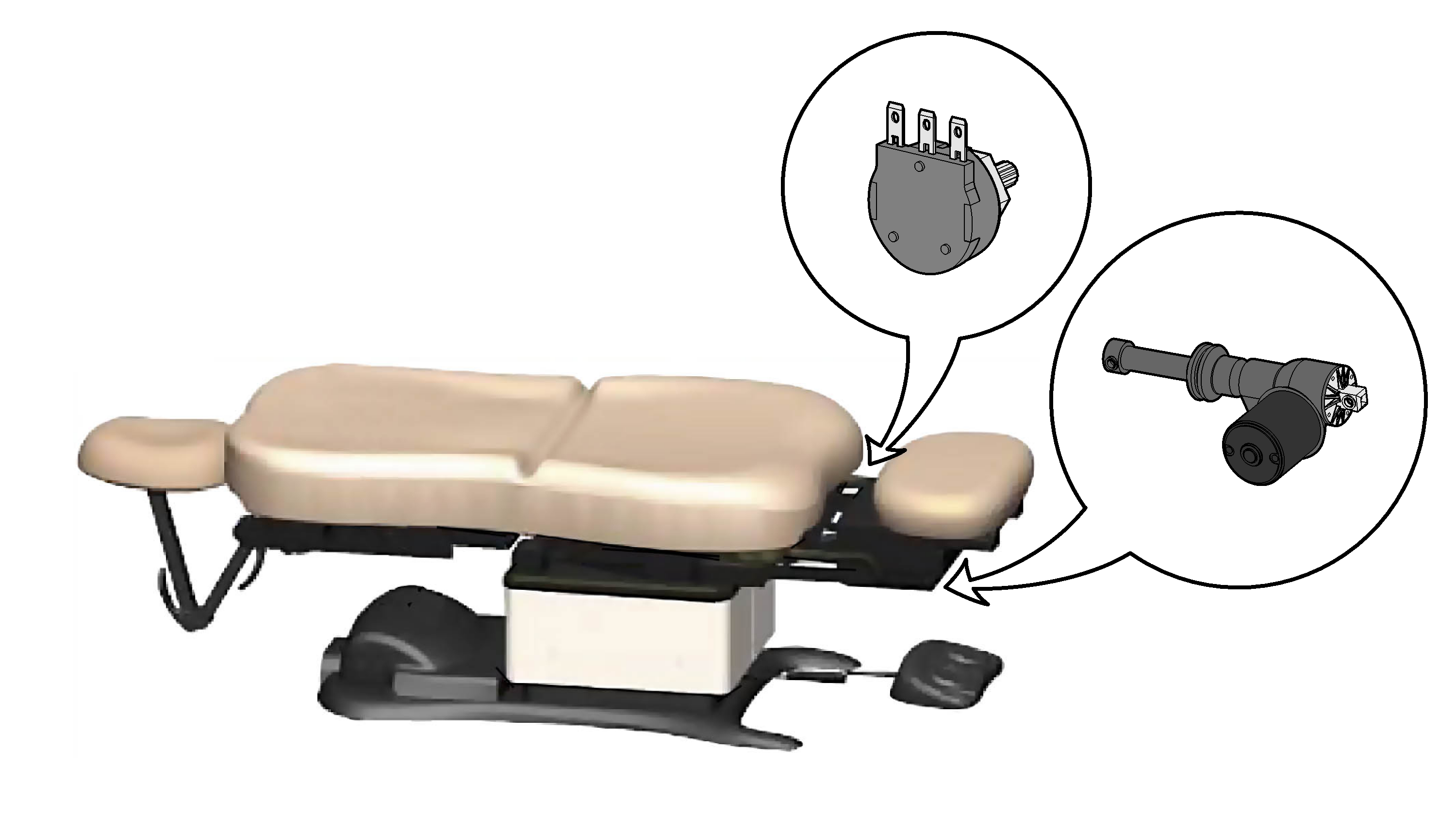
This illustration shows only the components that affect the Foot Up / Down function.
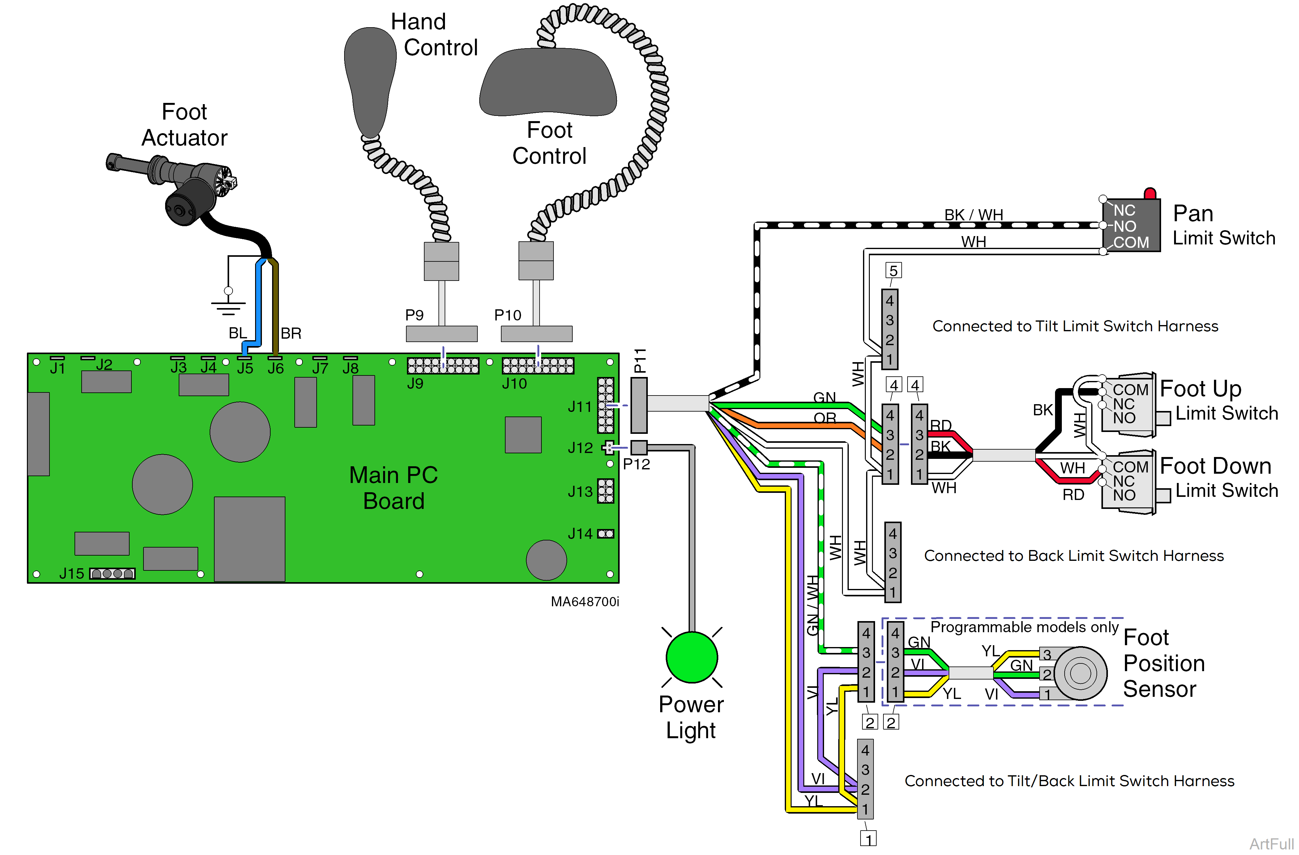
•If Power Light is On, proper voltage is present at PC Board.
•If Power Light is off, refer to Page A-2 for troubleshooting.
When voltage is present at the PC board, the power light is illuminated. Refer to: Power To The Chair for description of current flow to the PC board.
Circuitry on the PC board supplies 8-10 VAC to the hand / foot control connection ports.
When the Foot Up function is activated, current flows thru the hand / foot control, back to the PC board. Circuitry on the PC Board supplies approximately 48 VDC to the foot actuator motor.
The actuator motor runs and raises the foot section.
The PC board continuously monitors the Foot Up Limit Switch, the Pan Limit Switch, and the Foot position sensor*.
If the Foot Up Limit Switch is tripped (open), the Foot Up function will not operate.
When the treatment pan (located under the seat section) is pulled out, the Pan Limit Switch opens. If the Pan Limit Switch is open, the Foot Up function will not operate.
If the Foot position sensor* detects that the foot section has reached its upper limit, the Foot Up function will not operate.
Actuator Motor runs until
1.Hand / foot control button is released.
2.Foot Up limit switch is tripped.
3.Pan Limit Switch opens. Treatment pan is pulled out.
4.Emergency Stop button** is pressed.
5.Position Sensor malfunction*.
6.Overcurrent protection tripped.
7.Software time-out limit is reached, approximately 20 seconds.
Programmable models only.
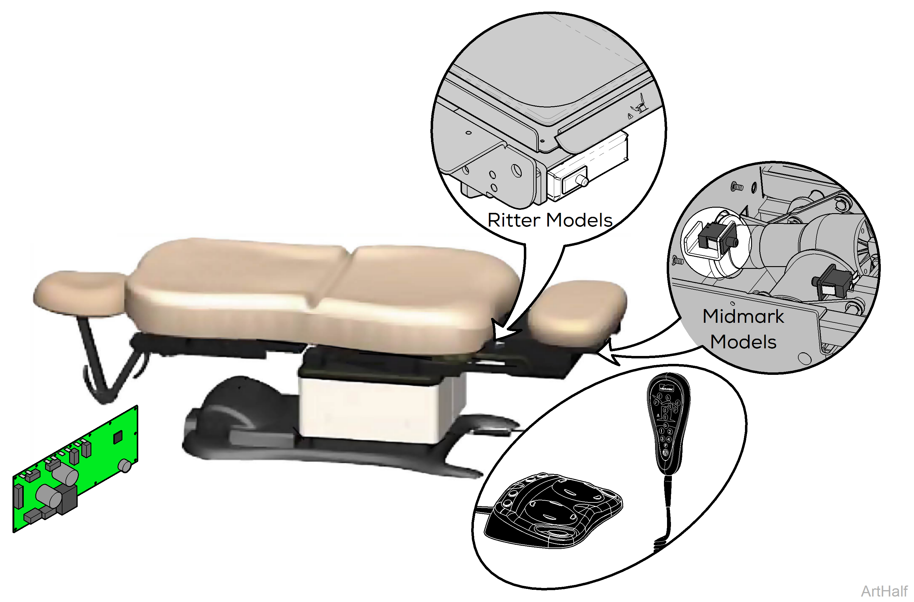
Midmark programmable models only. This feature is not available on Ritter models.
When the Foot Down function is activated, current flows thru the hand / foot control, back to the PC board. Circuitry on the PC Board supplies approximately 48 VDC to the foot actuator motor.
The actuator motor runs and lowers the foot section.
The PC board continuously monitors the Foot Down limit switch and the Foot position sensor*.
If the Foot Down limit switch is tripped (open), the Foot Down function will not operate.
If the Foot position sensor detects that the foot section has reached its lower limit, the Foot Down function will not operate.
Actuator Motor runs until
1.Hand / foot control button is released.
2.Foot Down limit switch is tripped.
3.Emergency Stop button** is pressed.
4.Position Sensor malfunction*.
5.Overcurrent protection tripped.
6.Software time-out limit is reached, approximately 20 seconds.
Programmable models only.
Midmark programmable models only. This feature is not available on Ritter models.
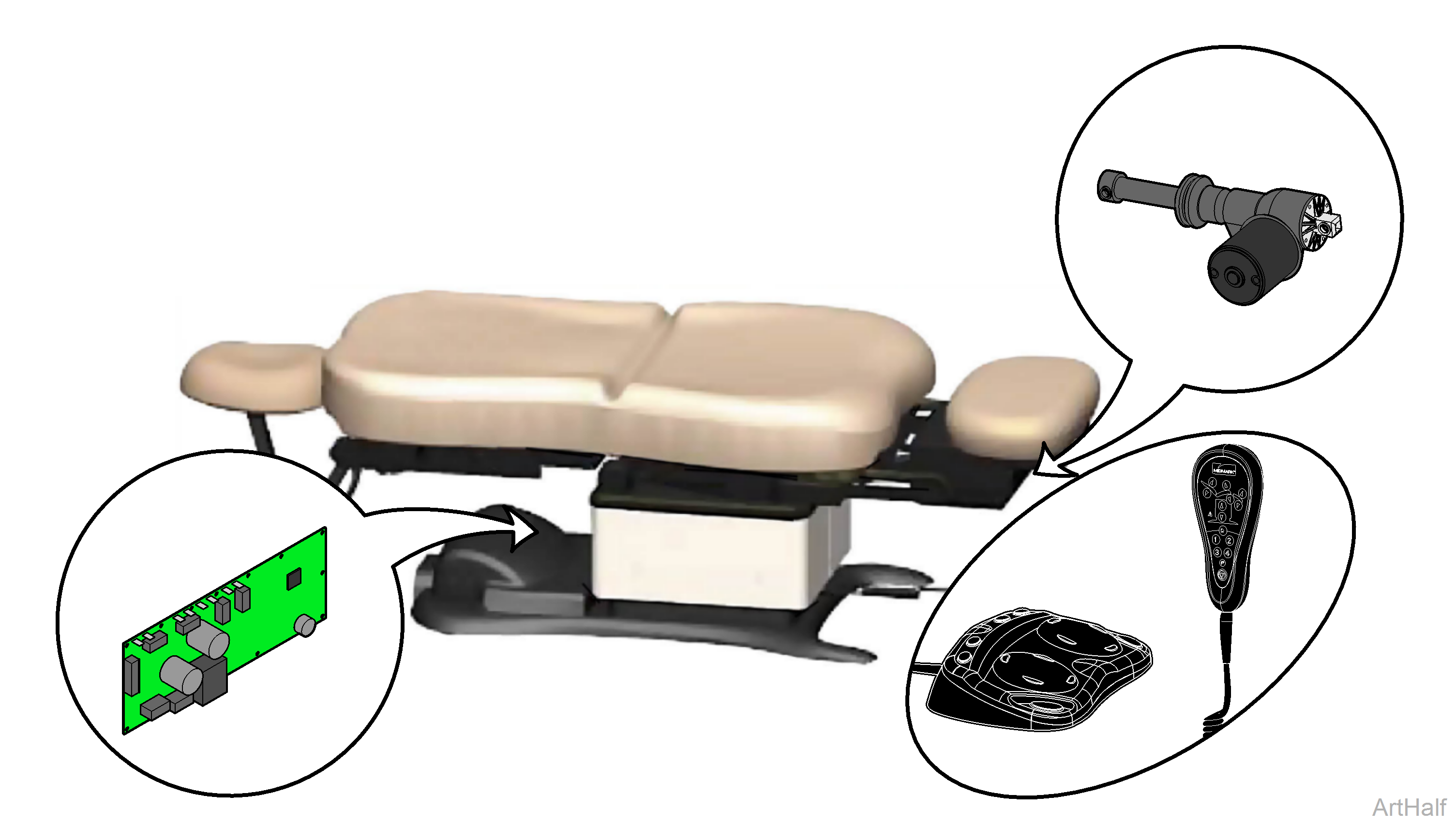
1.Loose / Damaged Wire Connections - Hand/Foot Control, Foot Actuator, and Foot Up/Down Limit Switches
2.Hand / Foot Control Refer to: Hand and Foot Controls
3.Foot Actuator Refer to: Foot Actuator
4.Main PC Board Refer to: Main PC Board
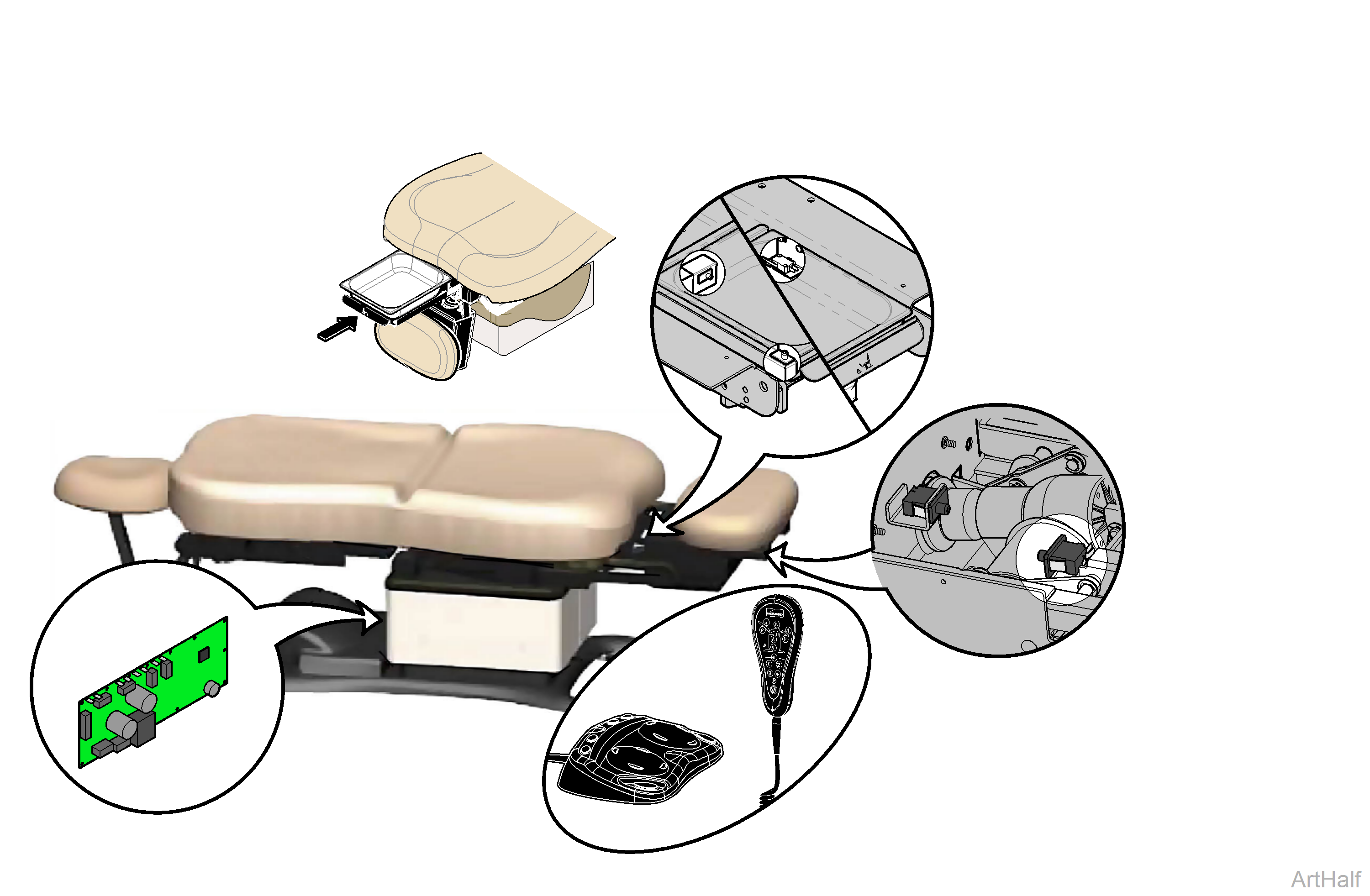
1.Pan Limit Switch Push Treatment Pan all the way in, then try again. Still no movement? Check Pan Limit Switch
2.Loose / Damaged Wire Connections - Hand/Foot Control, Foot Up and Pan Limit Switches
3.Foot Up Limit Switch Refer to: Limit Switches
4.Hand / Foot Control Refer to: Hand and Foot Controls
5.Main PC Board Refer to: Main PC Board
1.Loose / Damaged Wire Connections - Hand/Foot Control, Foot Down Limit Switch
2.Foot Down Limit Switch Refer to: Limit Switches
3.Hand / Foot Control Refer to: Hand and Foot Controls
4.Main PC Board Refer to: Main PC Board
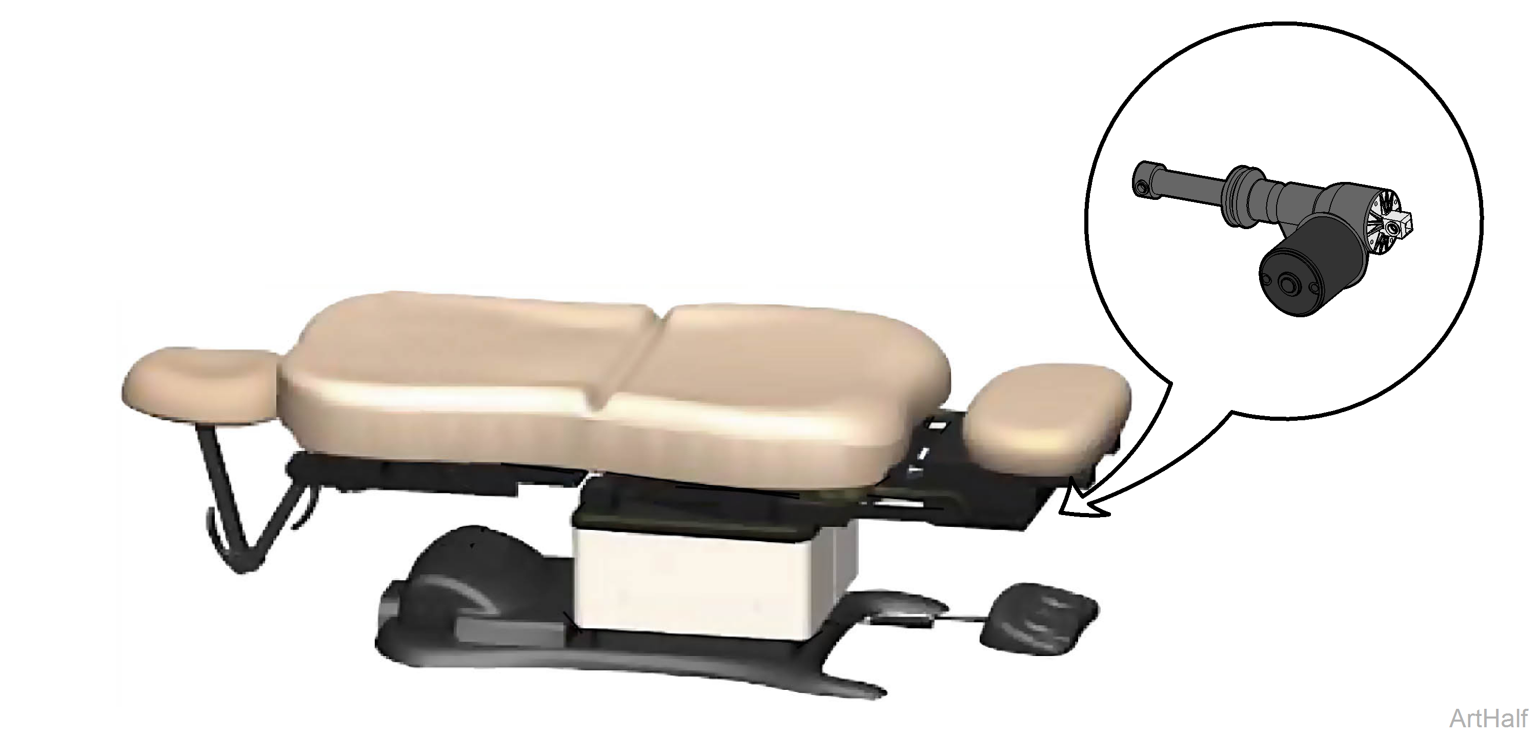
1.Foot Actuator Refer to: Foot Actuator
1.Foot Actuator Refer to: Foot Actuator
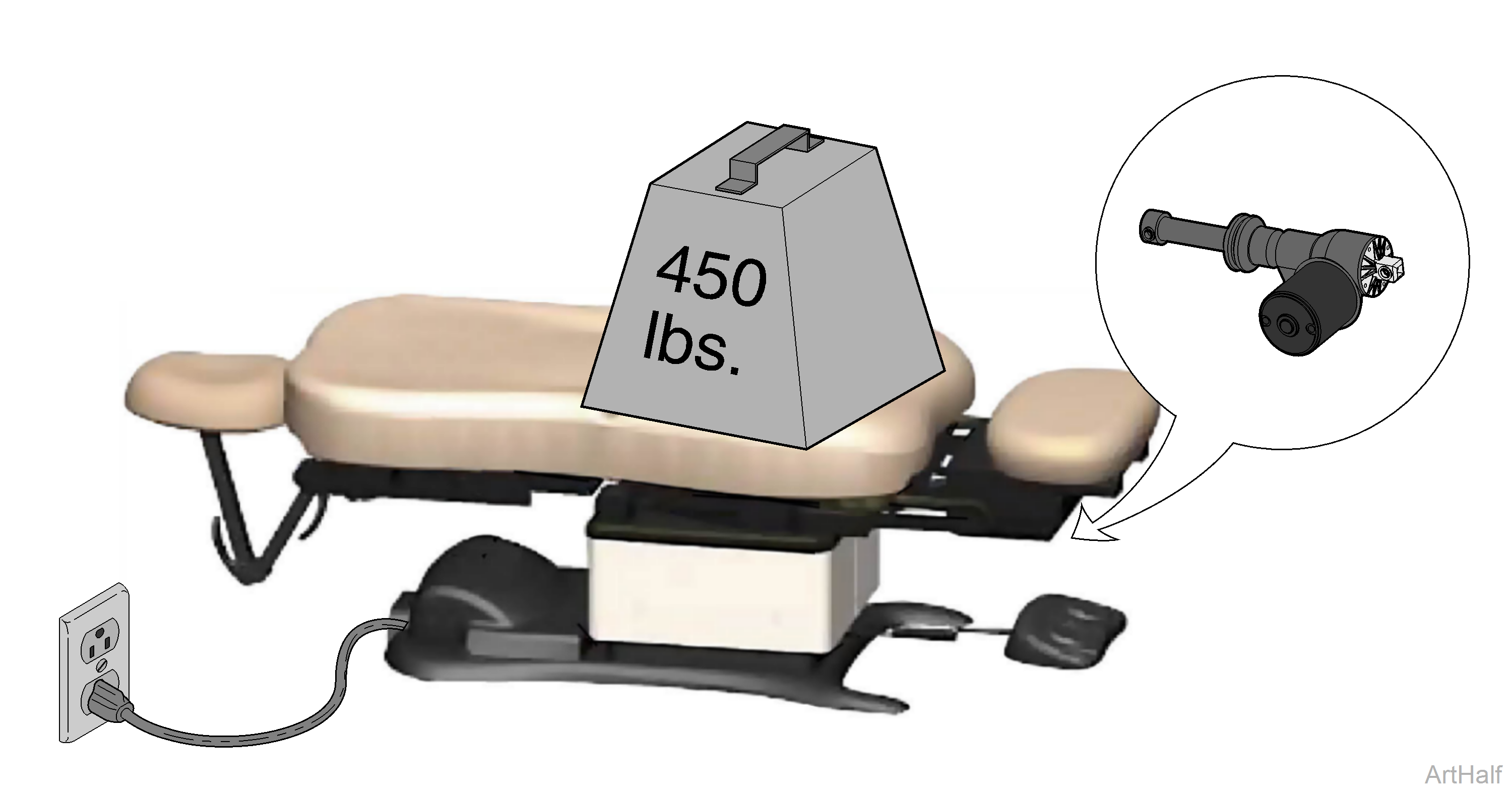
1.Did patient exceed 450 lb. weight limit? Inform staff that max. patient weight is 450 lbs. Refer to: Specifications
2.Low voltage to chair
| Required voltage: | |
|---|---|
|
115 VAC setting |
115 +10% VAC |
|
230 VAC setting |
230 +10% VAC |
3.Foot Actuator Refer to: Foot Actuator
1.Programmable models only: Calibrate PC Board Refer to: Main PC Board
2.Loose / Damaged Wire Connections - Refer to: Hand and Foot Controls, Foot Down Limit Switch
3.Programmable models only: Foot Position Sensor Refer to:Position Sensors
4.Foot Actuator Refer to: Foot Actuator
