Elevance® Delivery Handpiece Control Screens
For Endodontic Operations using Bien Air MX2 handpiece, ensure the bypass toggles are in the Normal position.
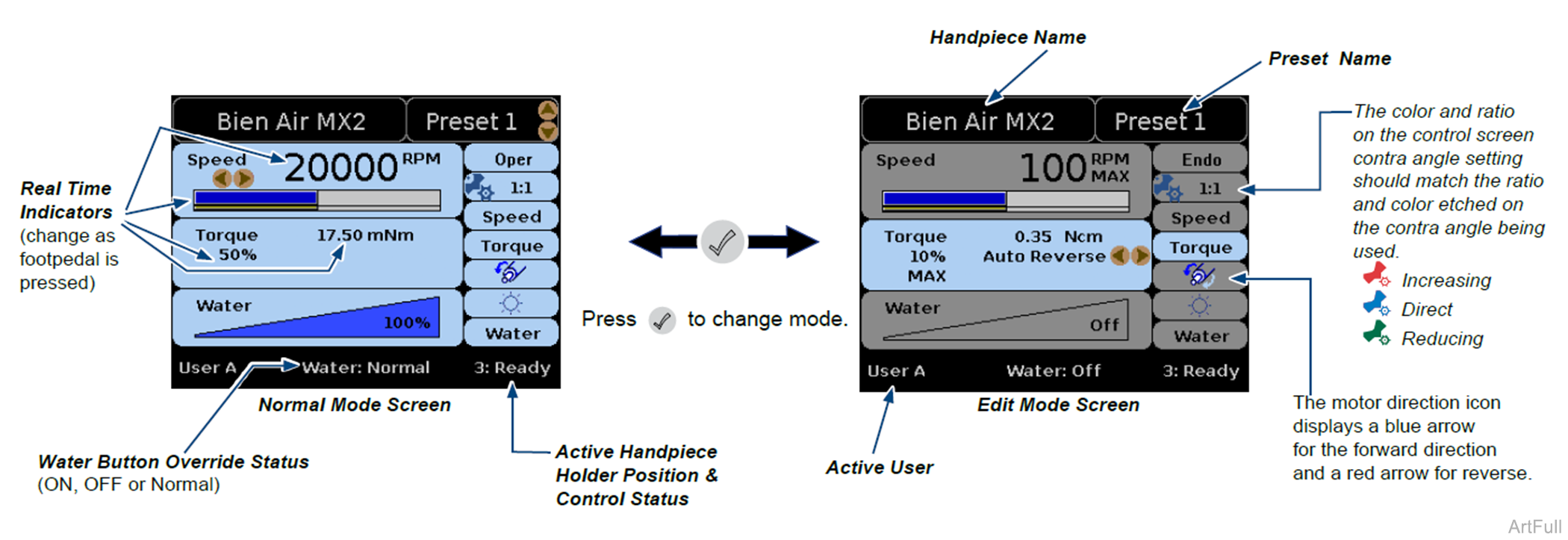
The normal mode control screen displays when a smart handpiece is pulled.
Use 
 to change Presets. The active preset name is displayed.
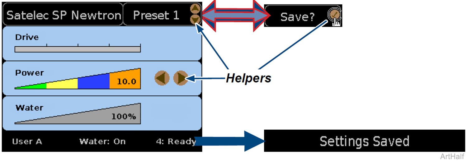
Helpers indicate the active controls (Preset and Speed control setting in example shown above).
Use 
 to change the speed control setting.
In Edit mode, the helpers appear beside the active setting and it becomes highlighted (Auto Reverse setting in example shown).
In Edit mode, use to move to a control setting.
Use to change the active control setting.
The Bien Air MX2 handpiece includes an endodontic mode of handpiece operation. Use to toggle between Endodontic/Operative operating modes when it is the active control setting on the Edit Screen. Endo mode is active in the Edit Mode Screen shown.
|
Screen |
When it Appears and What it Displays |
Information Conveyed |
|---|---|---|
|
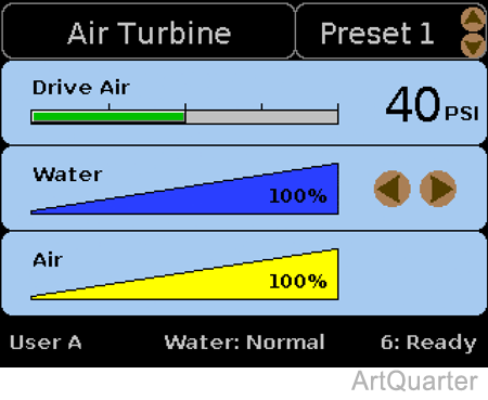
Air Turbine Control Screen - Normal Mode
|
Appears when an Air Turbine handpiece is pulled. Helpers appear beside active controls. Preset Name and Water setting in this example. Use Use Press Press Press |
Top Bar - Active Handpiece name and Preset name. Drive Air - a green indicator expands across the scale as the footpedal is pressed. A value also appears, indicating drive air delivered to handpiece. Water - blue color fills graphic to match % of water the control is set to. Air - yellow color fills graphic to match % of air the control is set to. Bottom Bar - Active user, water override status, handpiece position and status. |
|
Saving control settings when Auto Save Presets are turned off Modify setting(s). Press and hold A message flashes at the bottom of the screen to indicate, Settings Saved, then returns to normal. If you do not save the settings, "Save?" |
The default option is to Auto Save Presets, meaning as soon as you change a setting it automatically saves as the active preset for the active user. Turn the option On of Off from the User Setup Menu. |
|
|
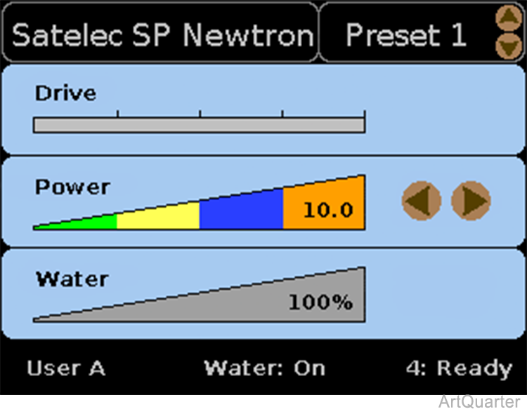
Satelec Scaler Control Screen - Normal Mode
|
Appears when an Satelec scaler handpiece is pulled. Helpers appear beside active controls (Preset Name and Power setting in this example). Use Use Press Press Press |
Top Bar - Active Handpiece name and Preset name. Drive - a green indicator expands across scale as the footpedal is pressed. Power - colors fill the graphic representing % of power delivered to the handpiece. Water - blue color fills graphic to match % of water the control is set to. Bottom Bar - Active user, water override status, handpiece holder position and control status. |
|
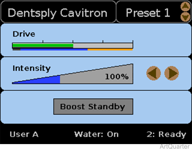
Dentsply Cavitron Scaler Control Screen - Normal Mode
|
Appears when a Cavitron scaler handpiece is pulled. Helpers appear beside active controls (Preset name and Intensity setting in this example). Use Use Press Press Press |
Top Bar - Active Handpiece name and Preset name. Drive - a green indicator expands across scale as the footpedal is pressed. The blue and orange colored bars may appear below the scale indicate the range when the boost is available (blue) and when the boost is active (orange). Intensity - blue color fills the graphic representing % of intensity delivered to handpiece. Boost status - notifies user when boost is available or in use. Bottom Bar - Active user, water override status, handpiece holder position and control status. |
|
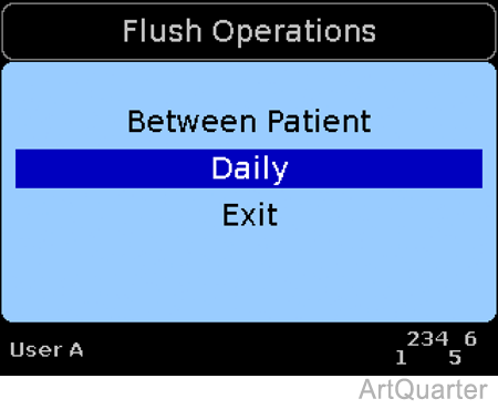
Flush Operations
|
Pull two or more smart handpieces at the same time and the Flush Operations menu appears.* Use Press Screens appear that are appropriate for the selected options. Always read the screens. User can change flush times using The Flush Process screen (not shown) displays a progress bar and a countdown timer as the flush function occurs. A Flush Complete screen (not shown) appears when finished. Return all handpieces to the holders, use *Except when Invert Handpiece Sensors option is active (see Diagnostics Menu below) |
Top Bar - flush screen name and/or flush cycle time. Message area - Lists options and/or operation status messages Bottom Bar - user name and handpieces pulled (top line). Handpieces remaining in holders appear on bottom line. Note: More details about performing Flush Operations appear in the Elevance Delivery User Guide. |
|
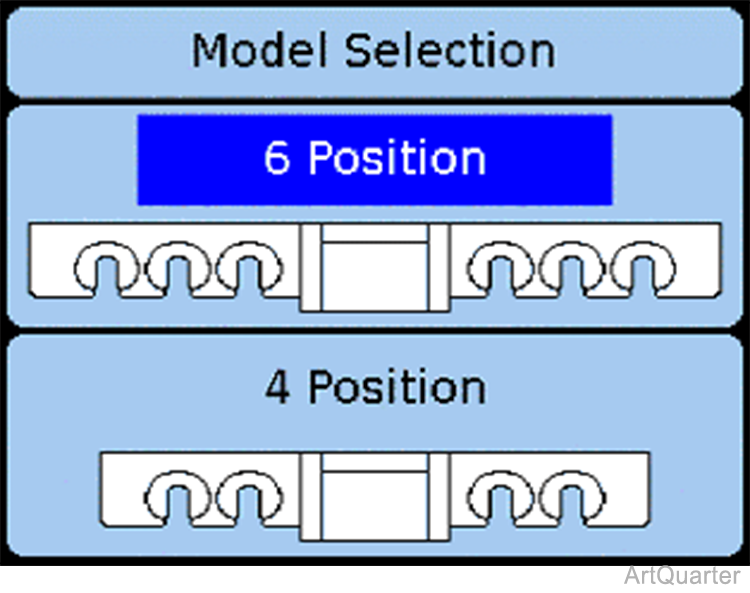
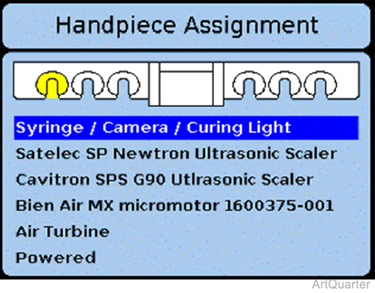
Configuration / Handpiece Assignment
|
Press Use The Handpiece Assignment Screen for that model appears. Press To assign a handpiece type to a holder position: Press Press Continue to press Note: The Powered option is not used. |
Verify handpiece position assignments and enable users to assign handpieces to new holder positions. |
|
Diagnostics Menu
|
Press Use Press Highlight the Invert Handpiece Sensors Option and press the Invert Handpiece Sensors On ( |
Displays Diagnostic options available. Offers option to Invert Handpiece Sensors to allow troubleshooting. Exit, returns to Home. |
|
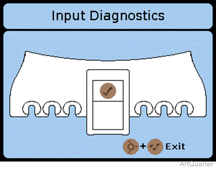
Input Diagnostics
|
Input Diagnostics Press any button on the control pad, pull any handpiece or actuate any e-field sensor on the delivery unit and an icon of that input illuminates, indicating that the sensor is functioning properly. Press |
Use to verify functionality of input sensors. Note: Control pad buttons do not function normally when Input Diagnostics screen is displayed. |
|
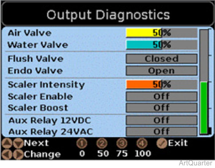
Output Diagnostics
|
Use Use Reference Helpers at the bottom of the screen to see the available options and button presses required for them. Drive Air can be input to the Interface Board via the foot pedal when the Air Valve is set to Pedal. Press |
Use to manually operate the Interface Board outputs. Knowing the status of the Interface Control Board output helps you to troubleshoot the components activated by those outputs. In Pedal mode you can activate multiple outputs you have set by all at one time by pressing the foot pedal. |
|
Display Diagnostics Gradient Screen
|
With Display Diagnostics highlighted on the Diagnostics Menu, press Use An all-white diagnostic screen is also available to check for dust / debris under the glass. |
There are no serviceable parts in the ICM. Return it to the manufacturer for replacement. |
|
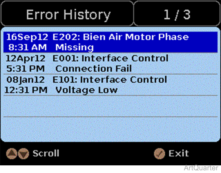
Error History
|
With Display Diagnostics highlighted on the Diagnostics Menu, press With Error History highlighted on the Diagnostics Menu, press If there are more errors than will fit on the screen, use Press |
Displays a list of the recorded errors. |
 to enter Edit mode (Screen not shown). In Edit mode, helpers move and a highlight appears on the active setting.
 to access the Configuration Screens.
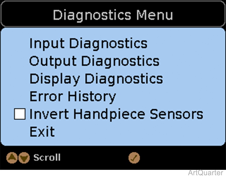
 and
and  = On ) or Off (
 = Off (default) ).