Midmark® Dental Halogen Light Bulb Socket Access Procedures
|
Mounted To |
Ceiling, Chair, Track, Universal and Wall/Cabinet |
| Serial Number | NW, RE and V Serial Number Prefixes |

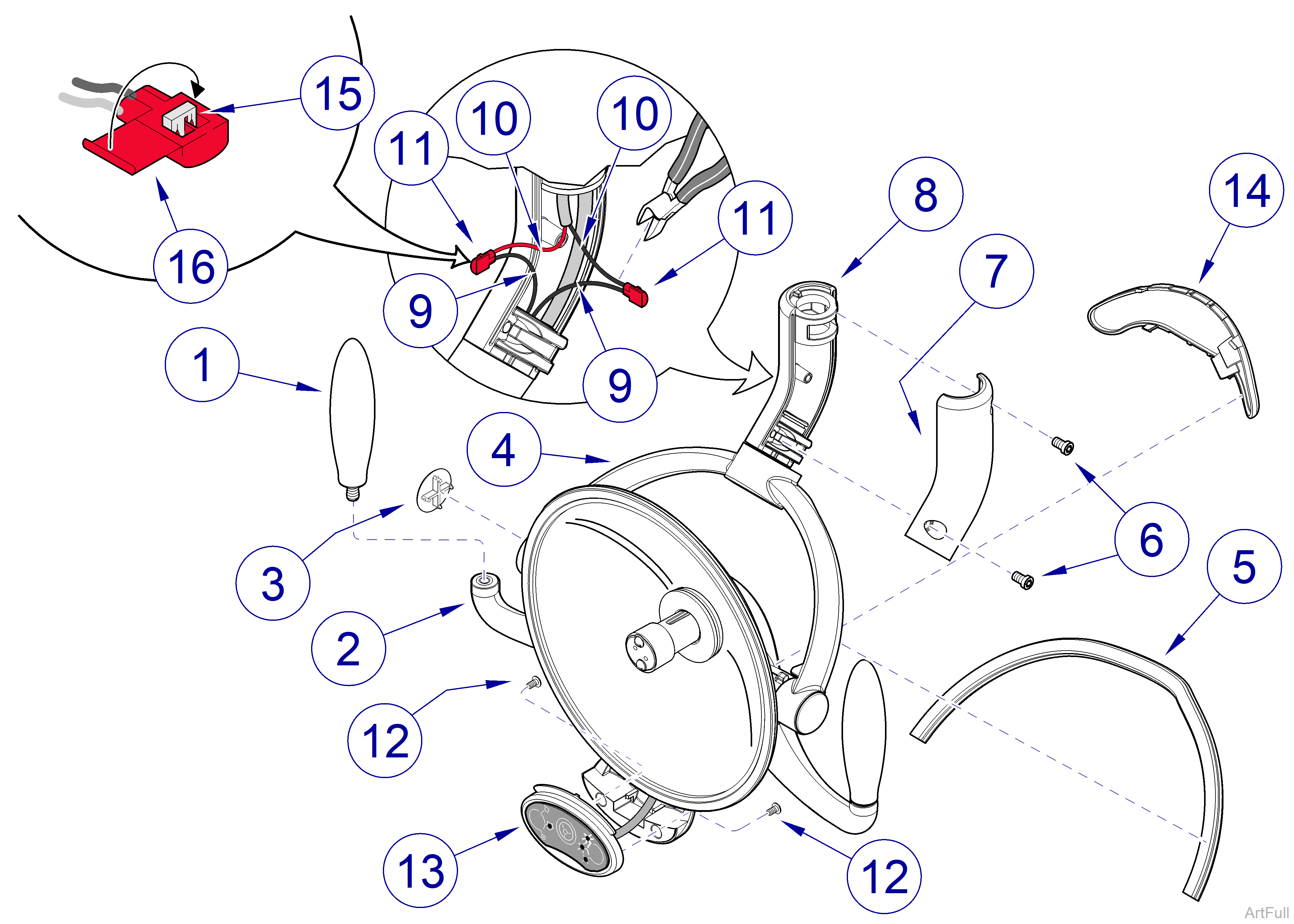
Figure 4-3: Covers Removal / Installation

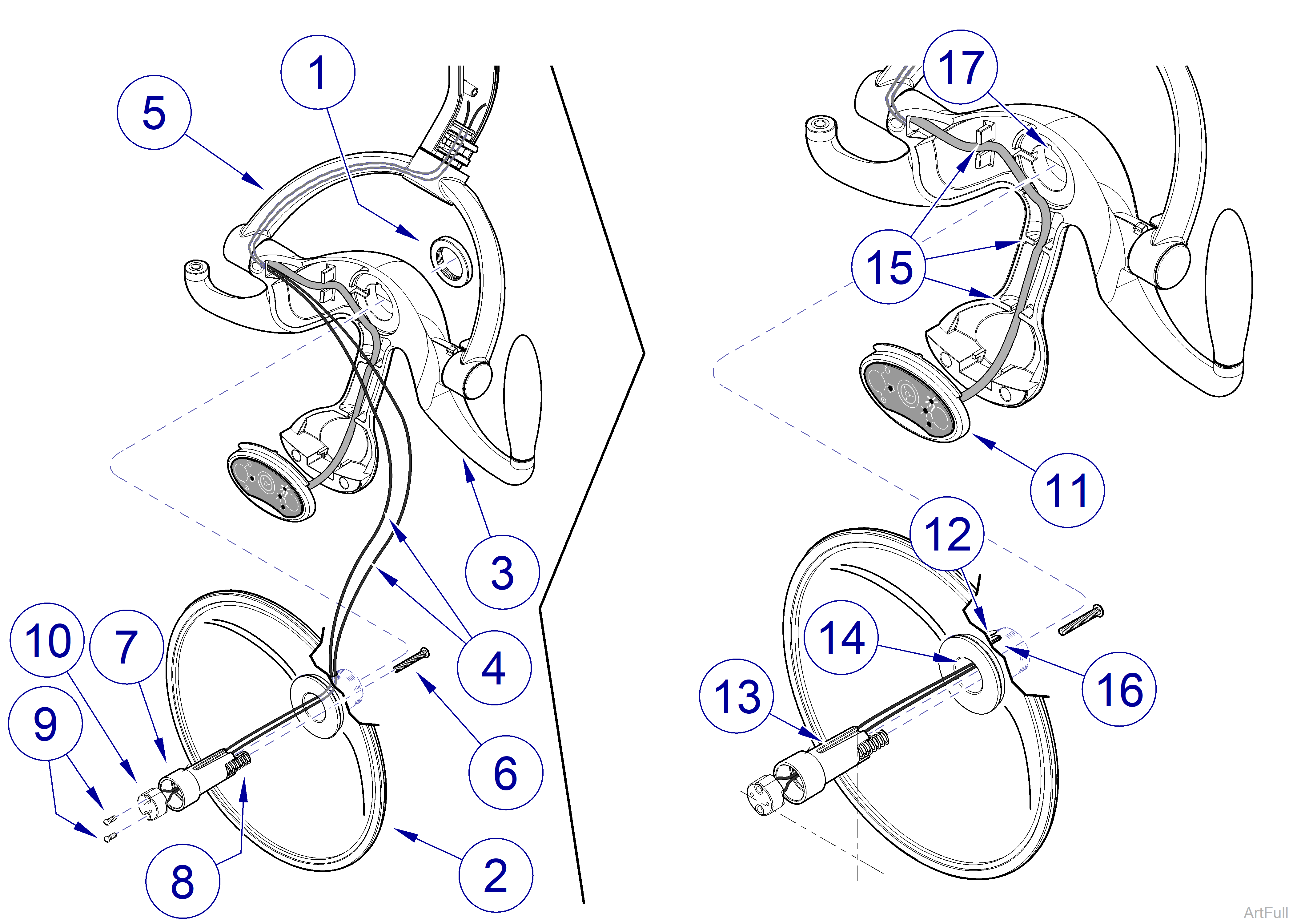
Figure 4-4: Bulb Socket Removal / Installation
Refer to: Midmark Dental Light User Guide for complete instructions on operating the light. Failure to do so could result in personal injury.
Perform an operational test on the dental light after repair is completed to confirm repair was properly made and that all malfunctions were repaired.
1.Remove light bulb. Refer to: Midmark® Dental Lights Bulb Access Procedures
2.Unscrew handle (1, Figure 4-3) from left side of reflector mount (2, Figure 4-3).
3.Using a thin bladed tool, pry yoke cap (3, Figure 4-3) from light yoke (4, Figure 4-3).
4.Remove yoke wire cap (5, Figure 4-3) from light yoke (4, Figure 4-3).
5.Remove two screws (6, Figure 4-3) and RH elbow half (7, Figure 4-3) from LH elbow half (8, Figure 4-3).
6.Cut wires (9 and 10, Figure 4-3) as close to wire connectors (11, Figure 4-3) as possible. Discard used wire connectors (11, Figure 4-3).
7.Remove two screws (12, Figure 4-3) and touchpad assembly (13, Figure 4-3) from reflector mount (2, Figure 4-3). Allow touchpad assembly to hang from wiring.
8.Using a thin bladed tool, pry focus cap (14, Figure 4-3) from reflector mount (2, Figure 4-3).
Spanner holes on focus housing nut are spaced approximately 1-3/16 in. (30.2 mm) apart. Snap ring pliers must be large enough to cover this distance.
9.Using a snap ring pliers or similar tool, remove focus housing nut (1, Figure 4-4). Refer to: Special Tool List
10.Pull reflector assembly (2, Figure 4-4) out front side of reflector mount (3, Figure 4-4) and then separate by carefully pulling two wires (4, Figure 4-4) out of reflector mount (3, Figure 4-4) and light yoke (5, Figure 4-4).
11.Remove focus screw (6, Figure 4-4), socket housing (7, Figure 4-4), and spring (8, Figure 4-4) from reflector assembly (2, Figure 4-4).
12.Remove two screws (9, Figure 4-4) and bulb socket (10, Figure 4-4) from socket housing (7, Figure 4-4).
Do not overtighten screws or bulb socket may crack. Also, bulb socket must be installed in correct orientation or light will not focus correctly.
1.While threading two wires (4, Figure 4-4) through bottom of socket housing (7, Figure 4-4), install bulb socket (10, Figure 4-4) in socket housing (7, Figure 4-4) and secure with two screws (9, Figure 4-4). Make sure bulb socket is oriented as shown in illustration.
In the following step, make sure to align slot (13, Figure 4-4) of socket housing (7, Figure 4-4) with key (14, Figure 4-4) of reflector assembly (2, Figure 4-4).
2.Insert spring (8, Figure 4-4) and socket housing (7, Figure 4-4) into reflector assembly (2, Figure 4-4), making sure to feed two wires (4, Figure 4-4) thru wire hole (12, Figure 4-4) in reflector assembly.
3.While pressing in on socket housing (7, Figure 4-4) to overcome spring (8, Figure 4-4) tension, install focus screw (6, Figure 4-4). Tighten focus screw fully, then back off two full turns.
During following step, make sure to align key (16, Figure 4-4) of reflector assembly (2, Figure 4-4) with slot (17, Figure 4-4) of reflector mount (3, Figure 4-4).
4.After feeding two wires (4, Figure 4-4) thru side of light yoke (5, Figure 4-4) and then making sure touchpad harness (11, Figure 4-4) is correctly positioned in four strain reliefs (15, Figure 4-4), install reflector assembly (2. Figure 4-4) on reflector mount (3, Figure 4-4) and secure with focus housing nut (1, Figure 4-4). Use snap ring pliers to tighten focus housing nut.
5.Feed two wires (9, Figure 4-3) through light yoke (4, Figure 4-3) so they can be connected to two wires (10, Figure 4-3).
Cut any excess length from two bulb socket (10, Figure 4-3) wires. Enough length should remain so that light head can pivot freely once wire connections are made.
To use wire connector, fully insert two unstripped wires into connector. Using pliers, squeeze wire spade (15, Figure 4-3) down onto two wires. Then, snap lid (16, Figure 4-3) shut to cover connections.
6.Connect one wire (9, Figure 4-3) to one wire (10, Figure 4-3) using new wire connector (11, Figure 4-3). Repeat for remaining set of wires (9 and 10, Figure 4-3).
7.Install RH elbow half (7, Figure 4-3) on LH elbow half (8, Figure 4-3) and secure with two screws (6, Figure 4-3). Adjust two screws while rotating lighthead around pivot joints. Lighthead should rotate through pivot joints easily without taking excessive force. When released, joints should not drift on their own. Adjust per user’s preference
8.Install yoke wire cap (5, Figure 4-3) on light yoke (4, Figure 4-3).
9.Install yoke cap (3, Figure 4-3) on light yoke (4, Figure 4-3).
10.Install touchpad assembly (13, Figure 4-3) on reflector mount (2, Figure 4-3) and secure with two screws (12, Figure 4-3).
11.Screw handle (1, Figure 4-3) onto left side of reflector mount (2, Figure 4-3).
12.Install light bulb. Refer to: Light Bulb Installation
13.Adjust focus pattern. Refer to: Halogen Light Beam Focus Adjustments
14.Install focus cap (14, Figure 4-3) on reflector mount (2, Figure 4-3).

