Midmark® Dental Lights Transformer Access Procedures
Refer to: Operator’s Manual for complete instructions on operating the light. Failure to do so could result in personal injury.
Perform an operational test on the dental light after repair is completed to confirm repair was properly made and that all malfunctions were repaired.
|
Mounted To |
Chair Units Powered w/ a Junction Box |
| Serial Number | NW, RE, and V Serial Number Prefixes |
1.Remove junction box cover. Refer to: Junction Box Removal
Always disconnect electrical power from the unit before removing any of the unit’s covers/shrouds or making any repairs to prevent the possibility of electrical shock. Failure to comply with these instructions could result in severe personal injury or death.
2.Unplug power cord of universal power supply from outlet receptacle.
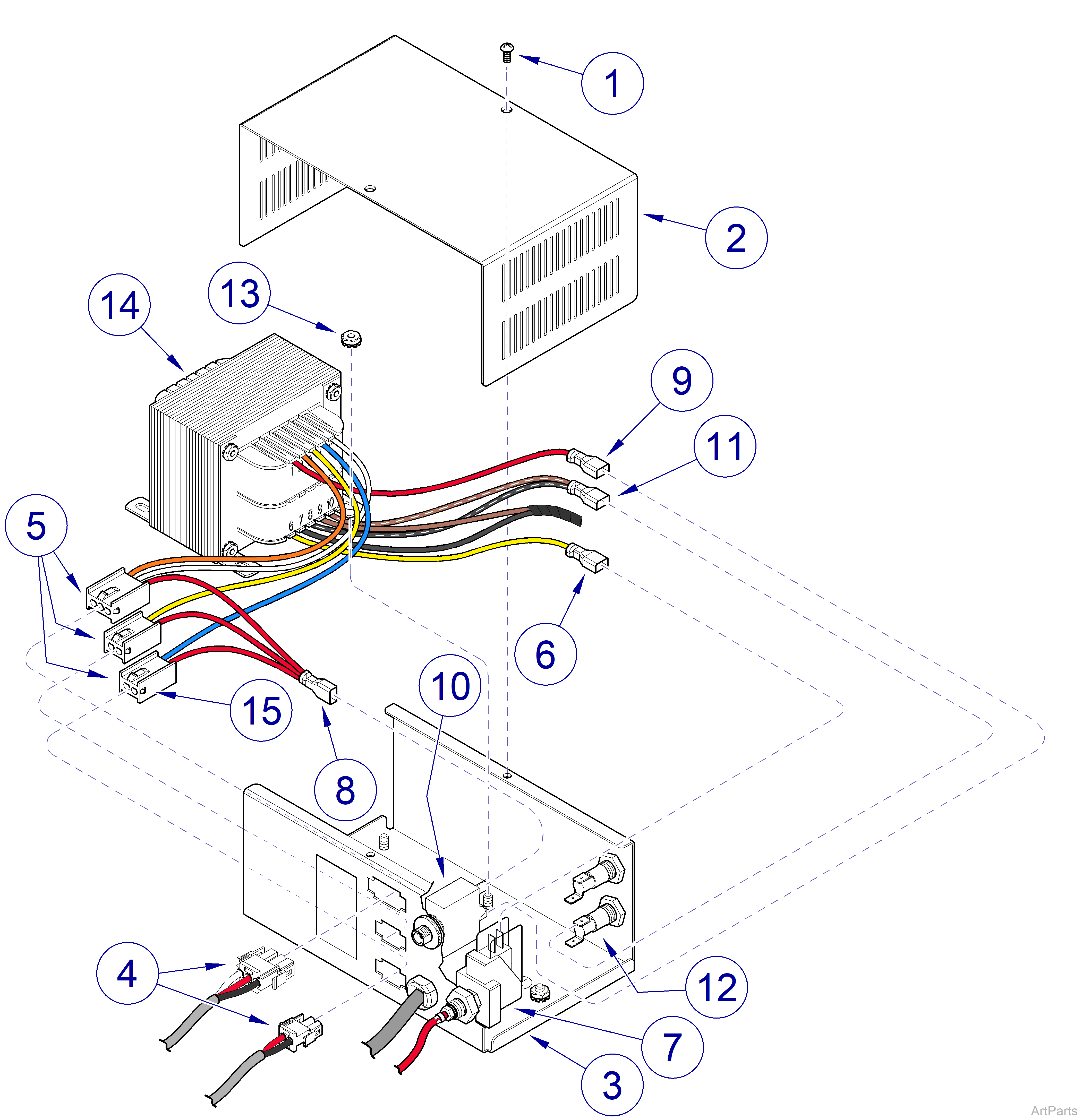
3.Remove two screws (1) and power supply cover (2) from chassis (3).
On some units, not all three wire harnesses will be connected, depending on which options were purchased.
4.Tag and disconnect wire harnesses (4) from connectors (5).
5.While pressing in on two locking tabs (15), push connector (5) out of chassis (3). Repeat for two remaining connectors (5).
6.Disconnect one wire (6) from center (N.O.) terminal of pressure switch (7).
7.Disconnect wire harness (8) and wire (9) from terminals of circuit breaker (10).
8.Disconnect wire harness (11) from terminal of fuse housing (12).
9.Remove four locknuts (13) and transformer assembly (14) from chassis (3).
1.Install transformer assembly (14) on chassis (3) and secure with four locknuts (13).
2.Connect wire harness (11) to terminal of fuse housing (12). If necessary, refer to Figure 5-2 for wiring diagram.
3.Connect wire harness (8) to top terminal and wire (9) to lower terminal of circuit breaker (10).
4.Connect one wire (6) to center (N.O.) terminal of pressure switch (7).
5.Install three connectors (5) in chassis (3) by pushing connectors into chassis until they “snap” into place.
On some units, not all three wire harnesses will be connected, depending on which options were purchased.
6.Connect wire harnesses (4) to connectors (5).
7.Install power supply cover (2) on chassis (3) and secure with two screws (1).
8.Plug power cord of universal power supply into outlet receptacle.
9.Install junction box cover. Refer to: Junction Box Installation
|
Mounted To |
Ceiling |
| Serial Number | NW, RE, and V Serial Number Prefixes |
Always disconnect electrical power from the unit before removing any of the unit’s covers/shrouds or making any repairs to prevent the possibility of electrical shock. Failure to comply with these instructions could result in severe personal injury or death.
1.Turn OFF facility power breaker so there is no power to light unit.
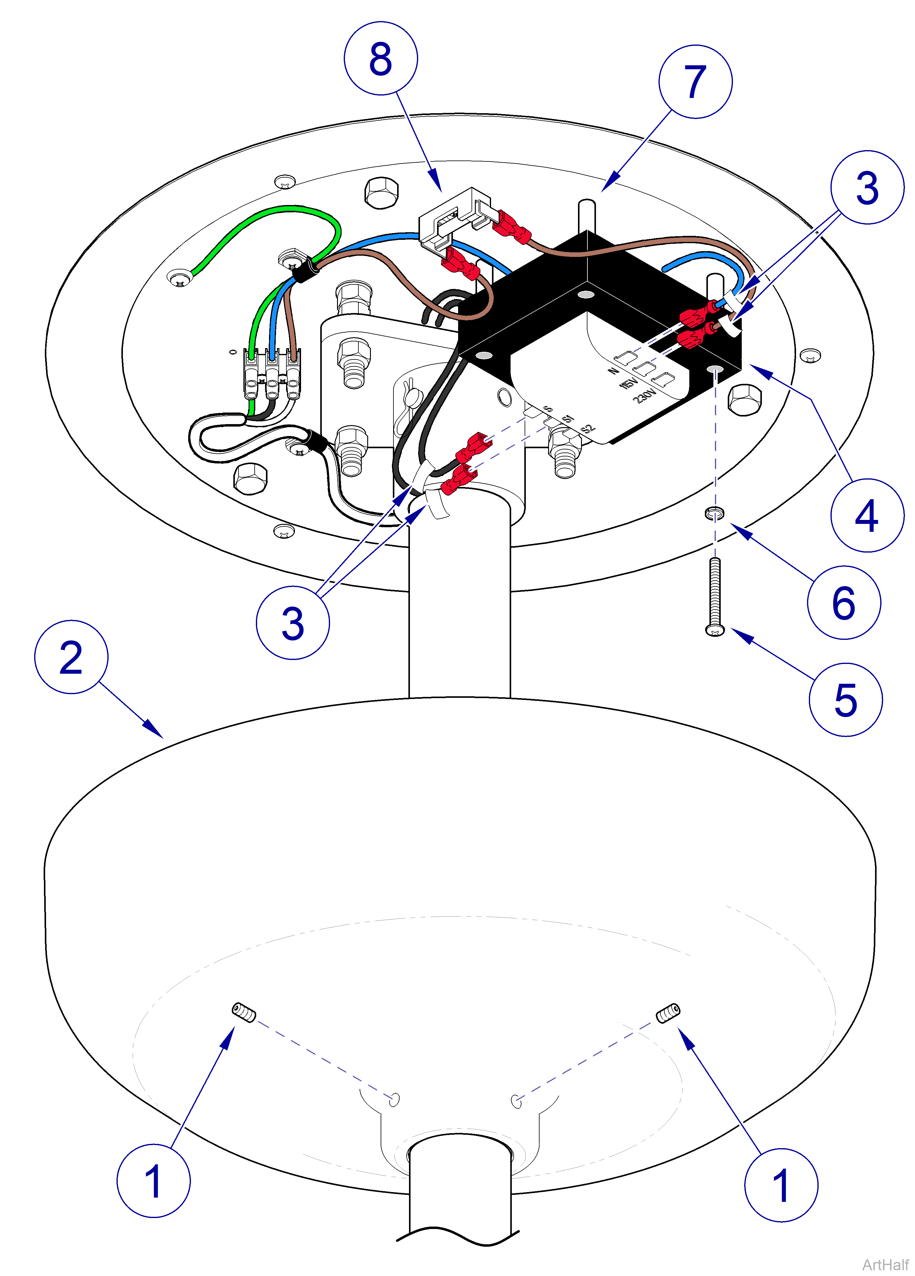
2.Loosen two setscrews (1) and lower ceiling cover (2) down out of way.
3.Tag and disconnect four wires (3) from terminals of transformer (4).
4.Remove four screws (5), lockwashers (6), transformer (4) and rolled spacers (7) from ceiling plate (8).
1.Install transformer (4) on ceiling plate (8) and secure with four rolled spacers (7), lockwashers (6), and screws (5).
2.Connect four wires (3) to terminals of transformer (4). If necessary, Refer to: Wiring Diagrams
3.Position ceiling cover (2) up against ceiling and then secure in position with two set screws (1).
4.Turn ON facility power breaker so there is power to light unit.
|
Mounted To |
Track |
| Serial Number | NW, RE, and V Serial Number Prefixes |
Always disconnect electrical power from the unit before removing any of the unit’s covers/shrouds or making any repairs to prevent the possibility of electrical shock. Failure to comply with these instructions could result in severe personal injury or death.
1.Turn OFF facility power breaker so there is no power to light unit.
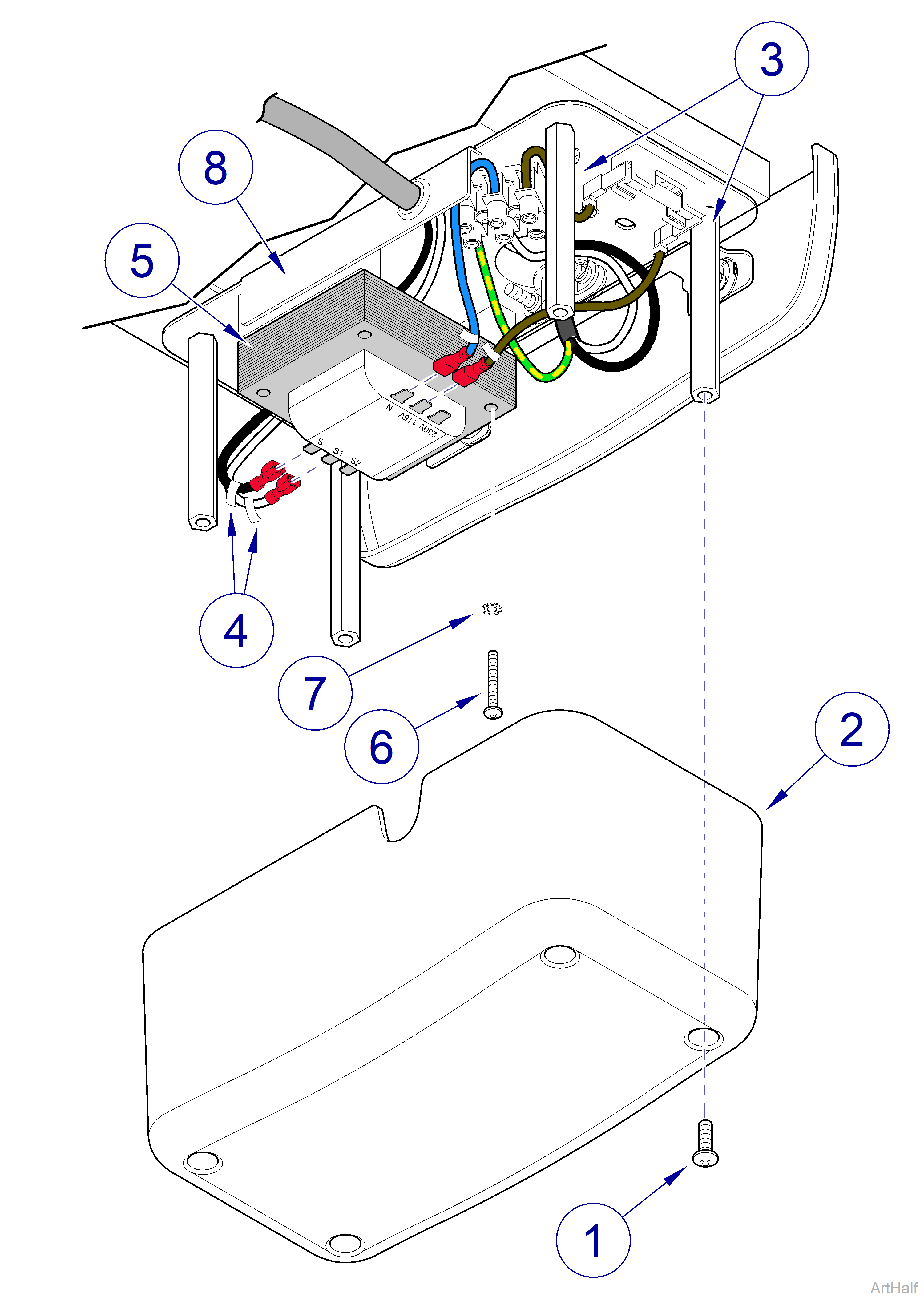
2.Remove four screws (1) and transformer cover (2) from standoffs (3).
3.Tag and disconnect four wires (4) from terminals of transformer (5).
4.Remove four screws (6), lockwashers (7), and transformer (5) from base plate assembly (8).
1.Install transformer (5) on base plate assembly (8) and secure with four lockwashers (7) and screws (6).
2.Connect four wires (4) to terminals of transformer (5). If necessary, Refer to: Wiring Diagrams
3.Install transformer cover (2) on four standoffs (3) with four screws (1).
4.Turn ON facility power breaker so there is power to light unit.
|
Mounted To |
Wall/Cabinet |
| Serial Number | NW, RE, and V Serial Number Prefixes |
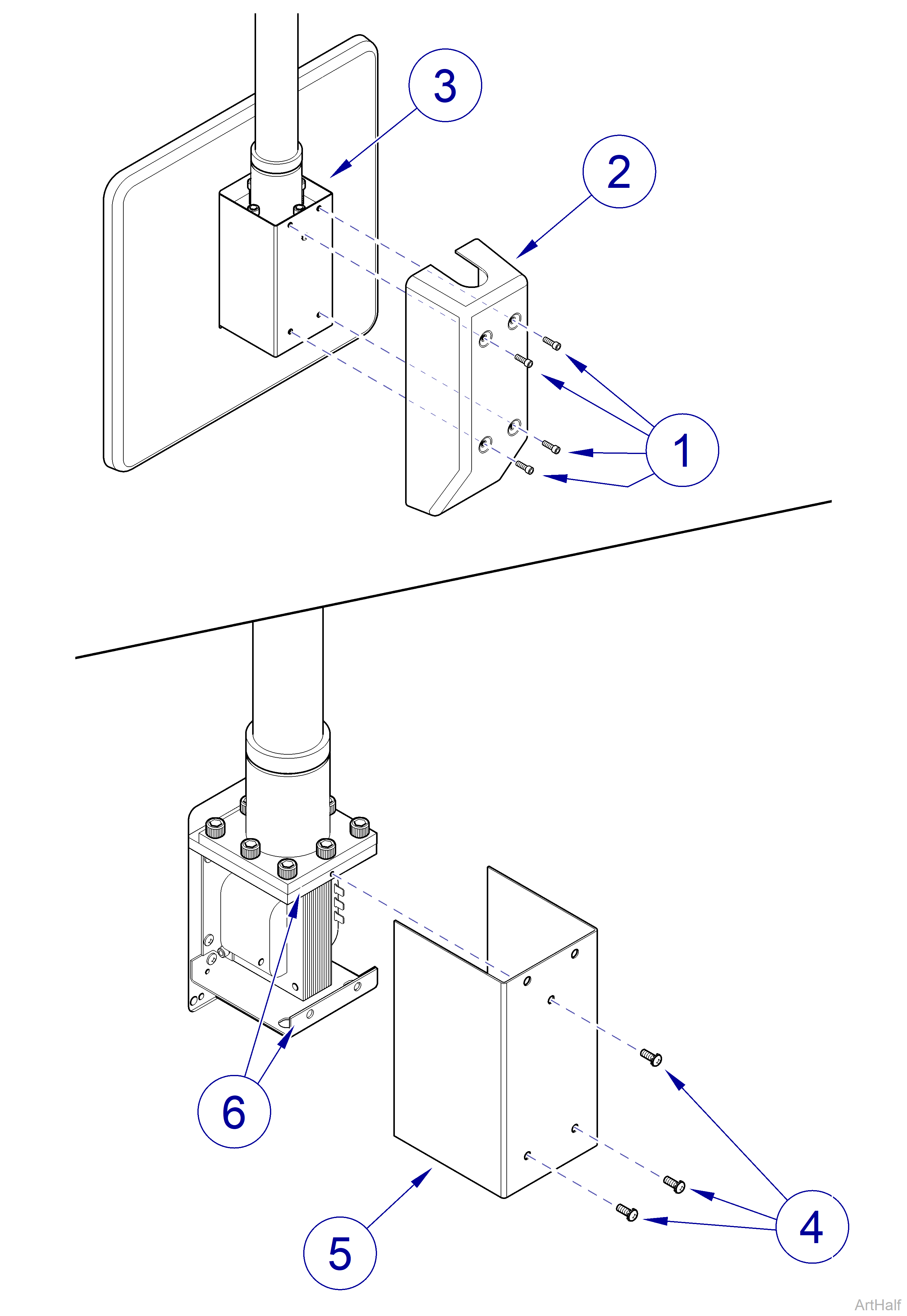
Figure 4-12
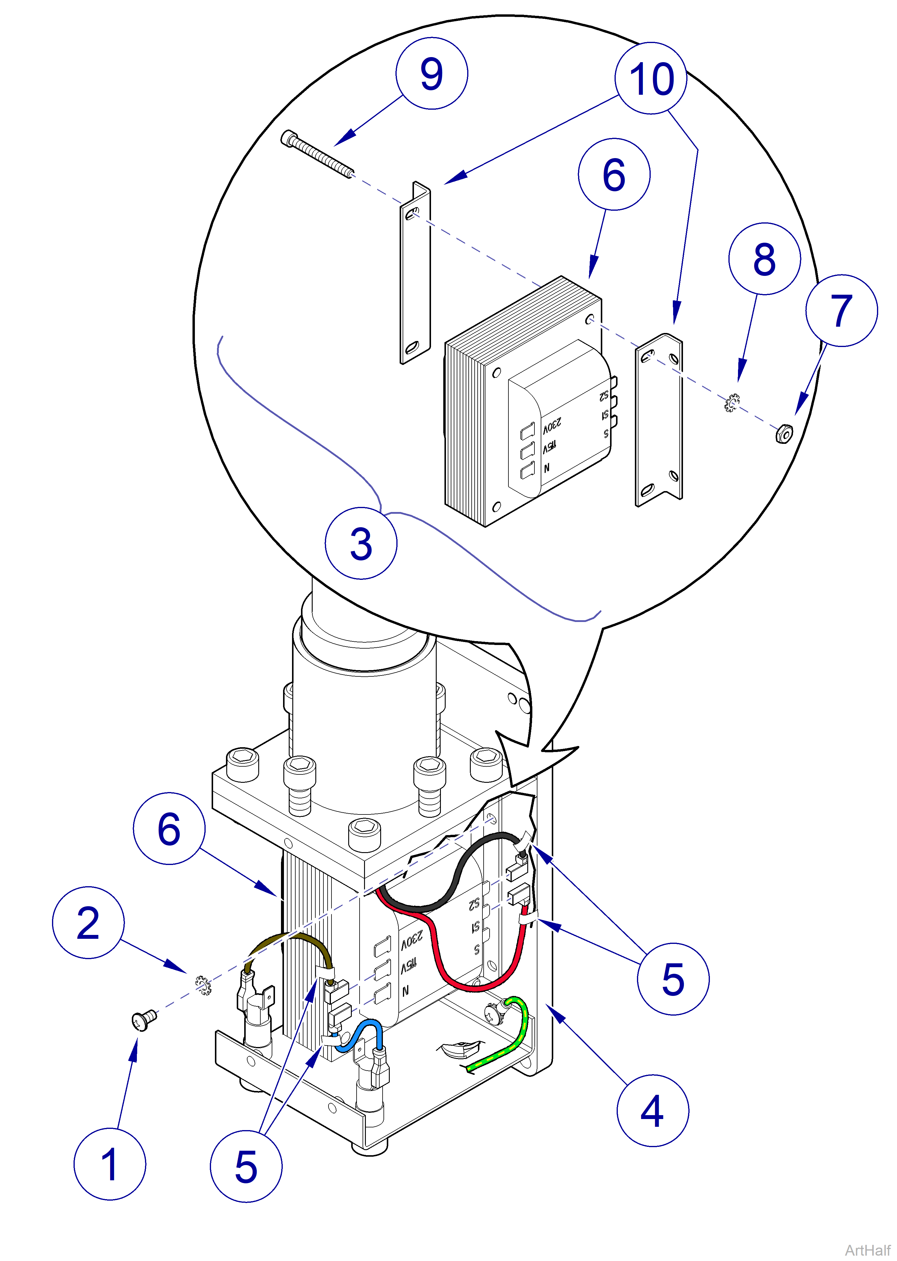
Figure 4-13
Always disconnect electrical power from the unit before removing any of the unit’s covers/shrouds or making any repairs to prevent the possibility of electrical shock. Failure to comply with these instructions could result in severe personal injury or death.
1.Turn OFF facility power breaker so there is no power to light unit.
2.If wall unit only, remove four screws (1, Figure 4-12) and transformer cover (2, Figure 4-12) from mount assembly (3, Figure 4-12).
3.Remove three screws (4, Figure 4-12) and cover assembly (5, Figure 4-12) from wall mount bracket (6, Figure 4-12).
4.Remove four screws (1, Figure 4-13), lock washers (2, Figure 4-13), and separate transformer assembly (3, Figure 4-13) from wall mount bracket (4, Figure 4-13).
5.Tag and disconnect four wires (5, Figure 4-13) from terminals of transformer (6, Figure 4-13).
6.Remove two nuts (7, Figure 4-13), lock washers (8, Figure 4-13), screws (9, Figure 4-13) and transformer brackets (10, Figure 4-13) from transformer (6, Figure 4-13).
1.Install transformer brackets (10, Figure 4-13) on transformer (6, Figure 4-13) and secure with two screws (9, Figure 4-13), lockwashers (8, Figure 4-13), and nuts (7, Figure 4-13).
2.Connect four wires (5, Figure 4-13) to terminals of trans former (6, Figure 4-13). If necessary, Refer to: Wiring Diagrams
3.Position transformer assembly (3, Figure 4-13) on wall mount bracket (4, Figure 4-13) and secure with four lock washers (2, Figure 4-13) and screws (1, Figure 4-13).
4.Install cover assembly (5, Figure 4-12) on wall mount bracket (6, Figure 4-12) and secure with three screws (4, Figure 4-12).
5.If wall unit only, install transformer cover (2, Figure 4-12) on mount assembly (3, Figure 4-12) and secure with four screws (1, Figure 4-12).
6.Turn ON facility power breaker so there is power to light unit.
|
Mounted To |
Universal |
| Serial Number | NW, RE, and V Serial Number Prefixes |
Always disconnect electrical power from the unit before removing any of the unit’s covers/shrouds or making any repairs to prevent the possibility of electrical shock. Failure to comply with these instructions could result in severe personal injury or death.
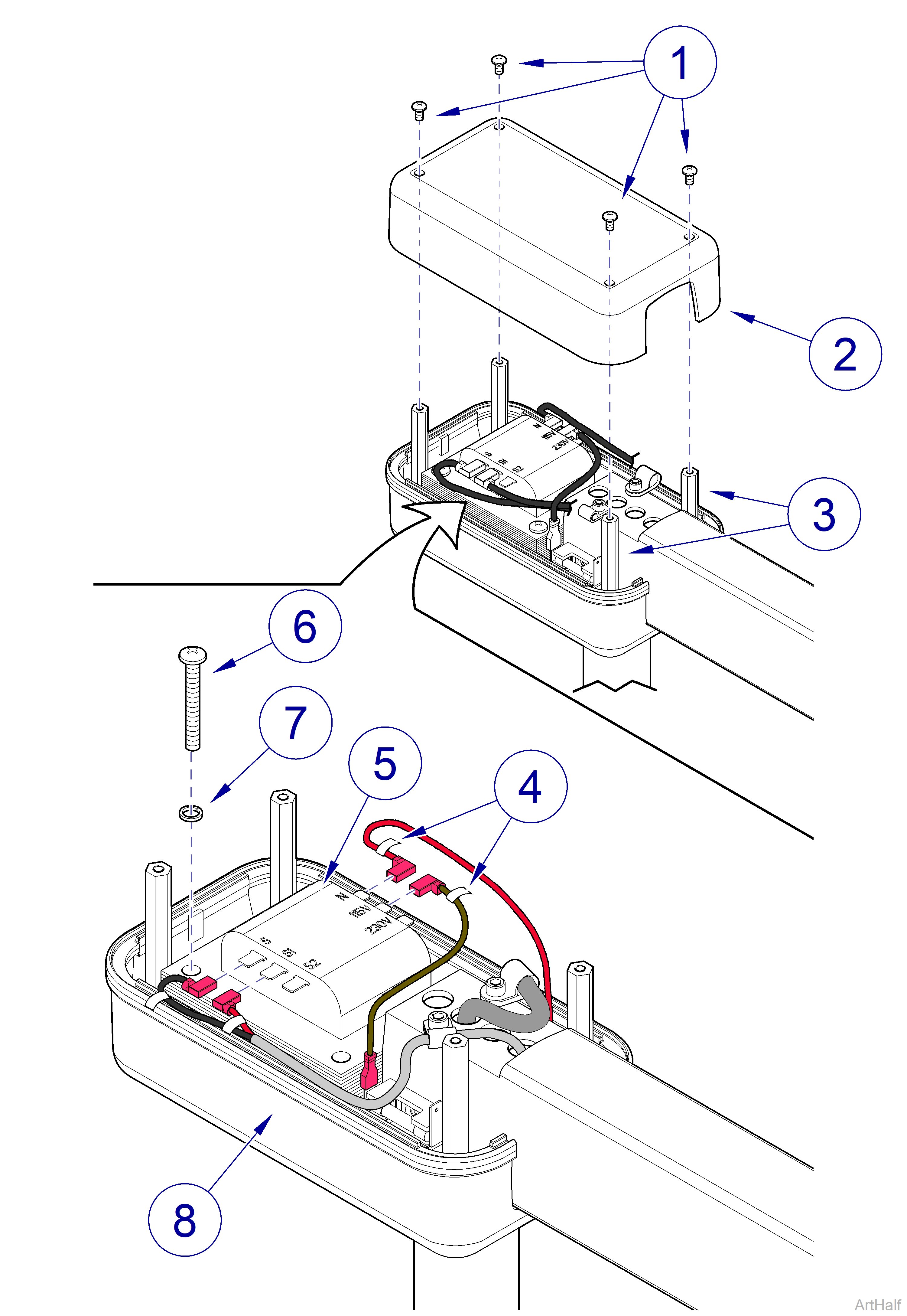
1.Turn OFF facility power breaker so there is no power to light unit.
2.Remove four screws (1) and top transformer cover (2) from standoffs (3).
3.Tag and disconnect four wires (4) from terminals of transformer (5).
4.Remove four screws (6), lockwashers (7), and transformer (5) from chassis assembly (8).
1.Install transformer (5) on chassis assembly (8) and secure with four lockwashers (7) and screws (6).
2.Connect four wires (4) to terminals of transformer (5). If necessary, Refer to: Wiring Diagram
3.Install transformer cover (2) on four standoffs (3) with four screws (1).
4.Turn ON facility power breaker so there is power to light unit.
