PowerVac G Motor and Pump Test and Repair
Motors are thermally protected with automatic reset. Unit may start without warning.
When working on Twin units, unplug parallel harness.
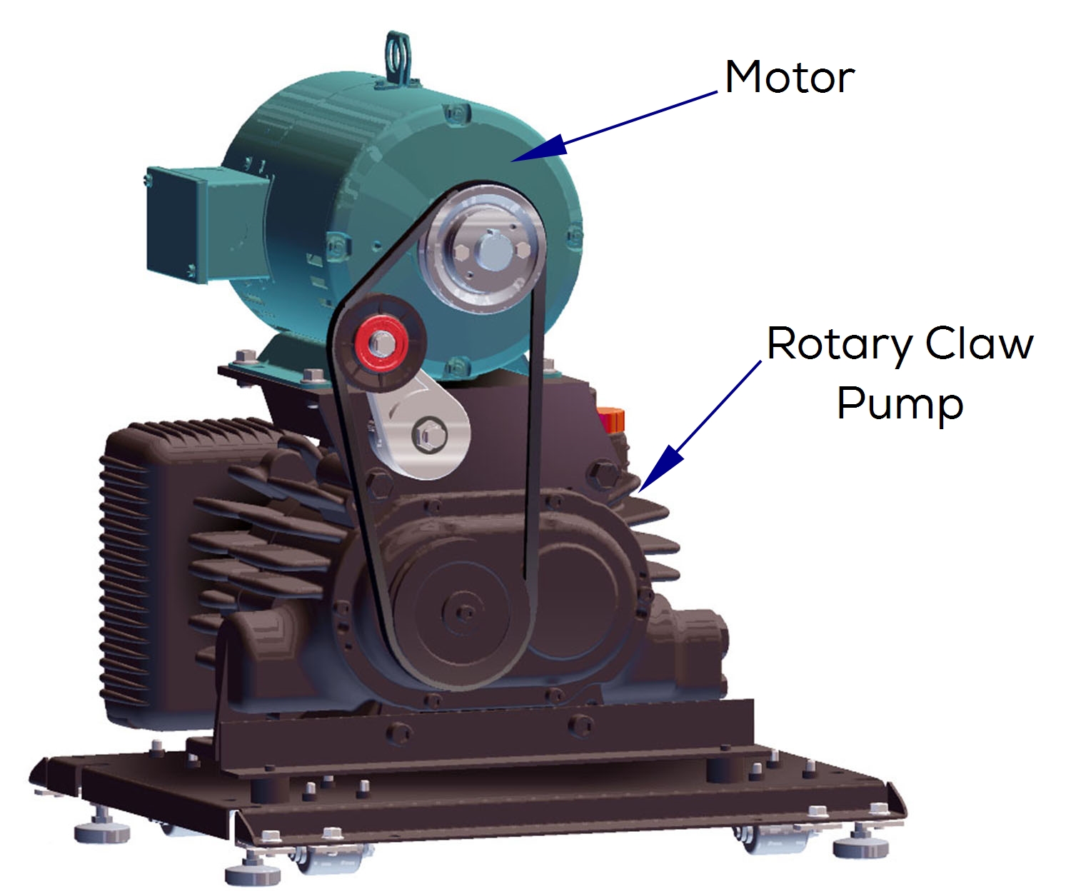
The 3 HP, three phase, 230 volt, electric motor is located on an adjustable motor mount and is easily accessible. There is an automatic belt tensioner within the pulley system.
The motor has a resettable thermostat that will open when the motor overheats. It is temperature controlled, so when it gets too hot it will open and when it cools off enough it will close again. Since the thermostat directly controls the state of the motor, there is no warning for when the motor will start or stop.
The dry vacuum pump requires no lubricant in the pumping chamber. The pump is a dual rotary claw type and belt-driven by the motor.
1.Turn power off at on/off switch and main power supply box.
2.Remove front cover. Refer to: Front Cover.
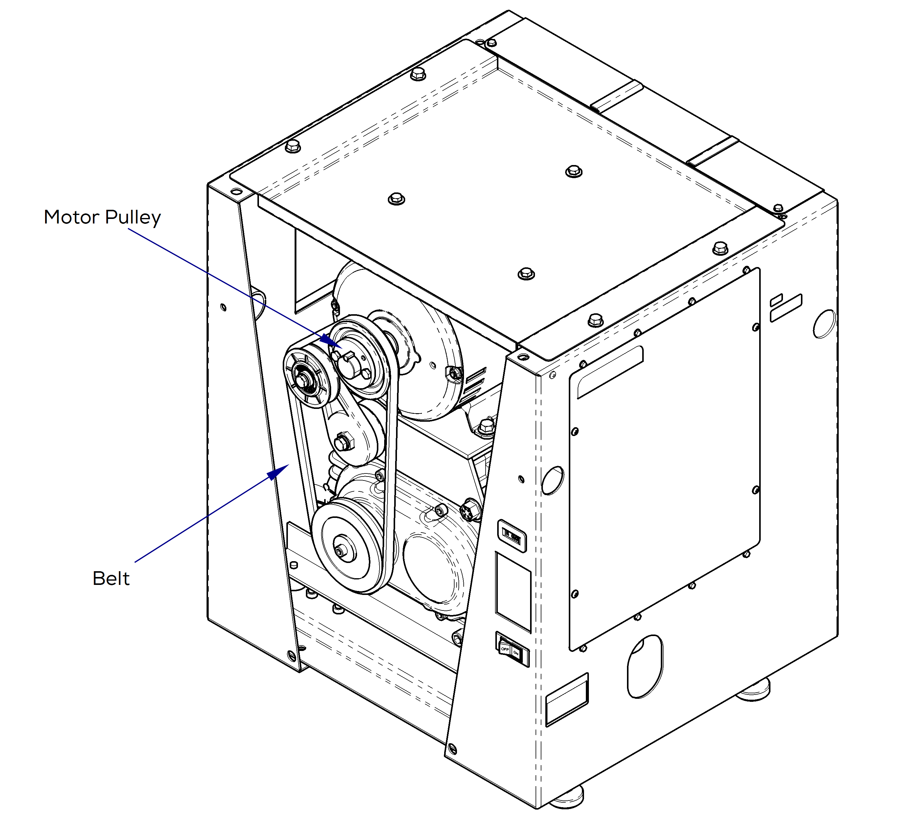
3.Use belt to check pulley. If locked up, try to work loose with belt.
4.If unable to work loose, remove belt.
5.Verify motor pulley moves freely. If not, motor bearing is locked up. Replace motor.
1.Turn power off at on/off switch and main power supply box.
2.Remove electrical cover.
3.Remove VFD covers.
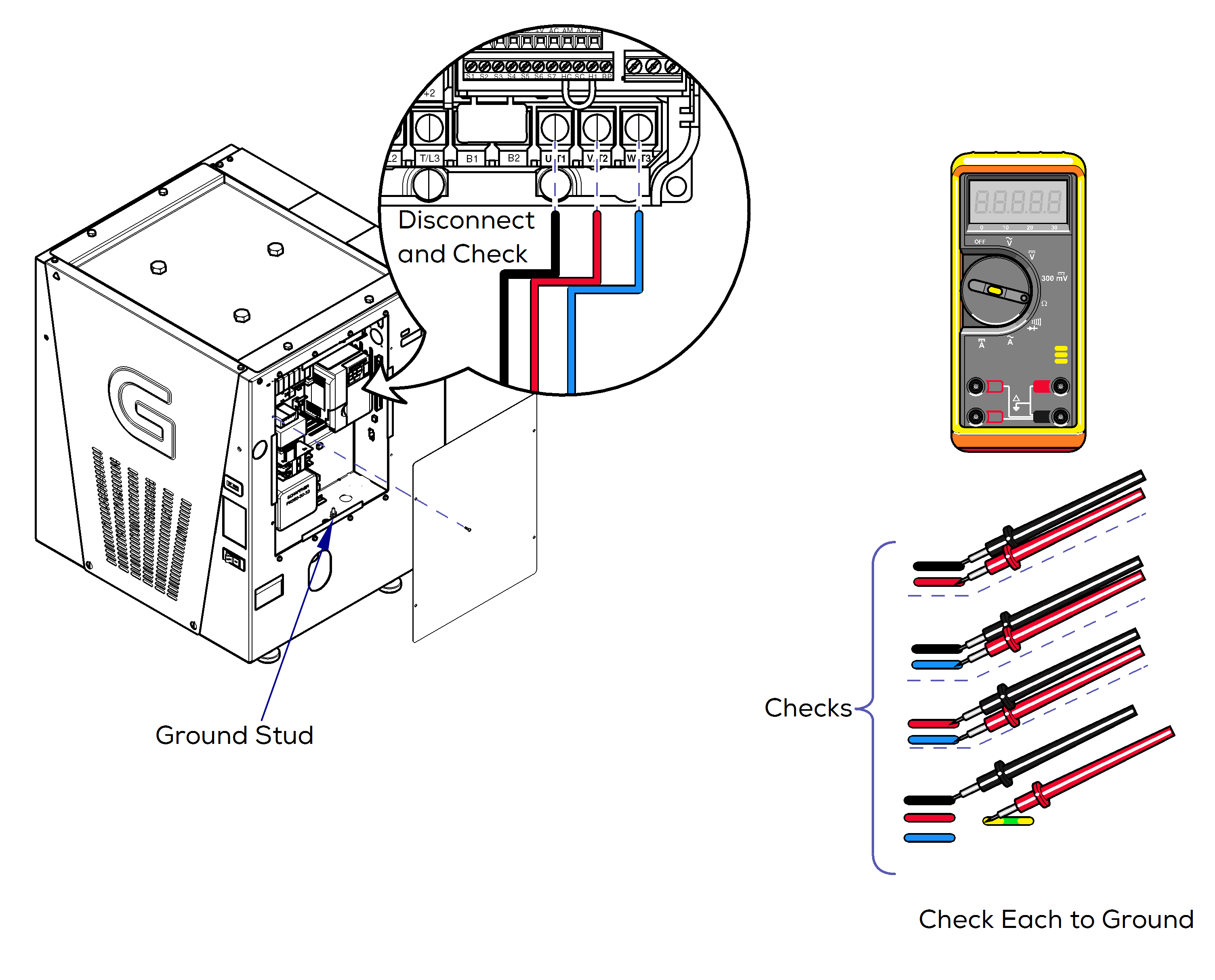
4.Set meter to Ω.
5.Disconnect wires from U/T1 (Black), V/T2 (Red), and W/T3 (Blue).
6.Check wire connections, Black to Red, Black to Blue, and Red to Blue.
7.Check ground connections, Black to Ground, Red to Ground, and Blue to Ground.
Refer to: Wire Diagrams, Electrical Cover, and VFD. If checks are out of range and if all probable causes for motor not running have been checked and the motor still doesn’t run, replace motor. Refer to: Troubleshooting Chart
|
Check |
Meter Reading |
Required Action |
|---|---|---|
|
Wire connections |
1.2 +/- .3 ohms |
Motor OK |
|
Ground connections |
OL |
Motor OK |
1.Turn power off at on/off switch and main power supply box.
2.Check pulley to see if locked up. Use belt to check pulley. Try to work pulley loose, turn with hand. If pulley does not move, continue next steps.
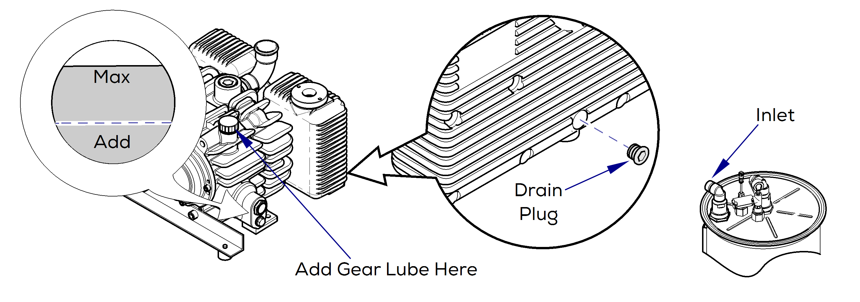
3.Check gear lubricant level. Add if below 1/3 full. Use only Midmark gear lube P/N 002-1999-00.
If gear lube is not light yellow / clear opaque color, it will need to be changed. Refer to: Change gear lube.
4.Check for water in pump. Remove drain bolt off pump and barb fitting at the bottom of the p-trap to release any water inside. When pump and P-trap is done draining, replace drain bolt and the barb fitting.
Water may flood out, set funnel under bolt hole to move water from pump into a bucket or tray.
5.After draining, remove inlet hose either at pump or at separator.
6. Pour 2 ounces (1/4 cup) of conditioning fluid (002-1910-02) into pump and let soak or WD-40 if unavailable.
7.Try to work pulley loose as fluid migrates through pump. If pump will not free up, order Timer/Conditioning Fluid Kit (002-1910-00) and socket (002-1911-00). If pump rotates freely, replace inlet hose, restore power, and start vacuum. Order Timer/Conditioning Fluid Kit if needed.
The gear lube should be changed every 10 years. It will hold approximately 2/3 of a quart of Midmark PN 064-0028 which can be ordered in a liter.
1.Run unit for 5-10 minutes.
2.Disconnect main power supply.
3.Remove front cover. Refer to: Front Cover
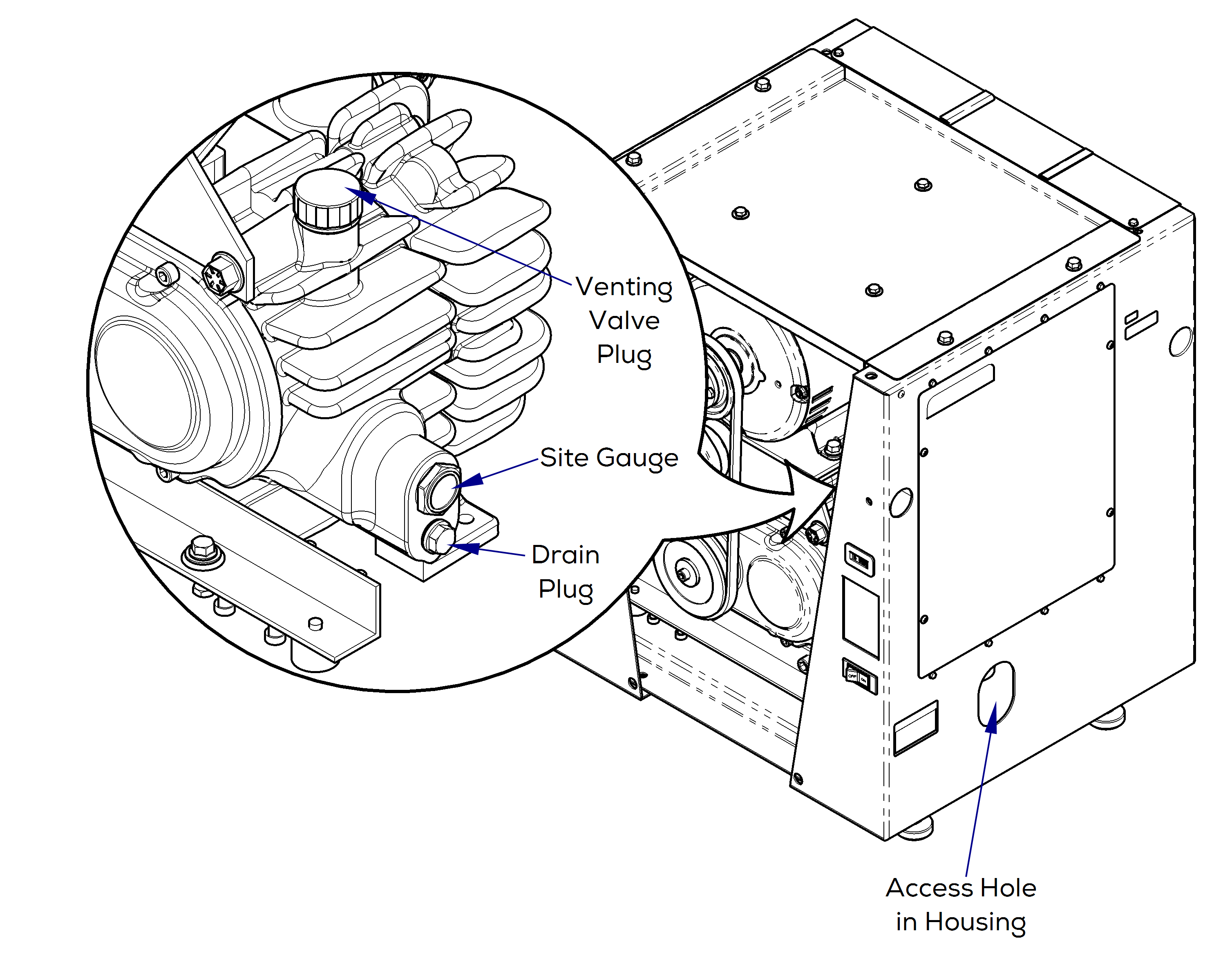
4.Remove venting valve plug.
5.Siphon gear lube out from venting valve hole.
If you do not have a siphon hose, you may access the drain plug located below the sight gauge. Place an oil absorbent mat under drain hole and funnel the gear lube out the side access hole in housing into a drain tray. Dispose of gear lube in compliance with applicable regulations.
6.Fill in new gear lube until the level is slightly above the middle of the sight gauge.
7.Verify seal ring on vent valve is undamaged.
8.Replace vent valve plug and or drain plug. See note above.
9.Clean any gear lube that leaked on inside or outside of housing.
10.Replace front cover. Connect main power supply and run pump for 5 minutes and recheck the gear lube on the sight gauge.
