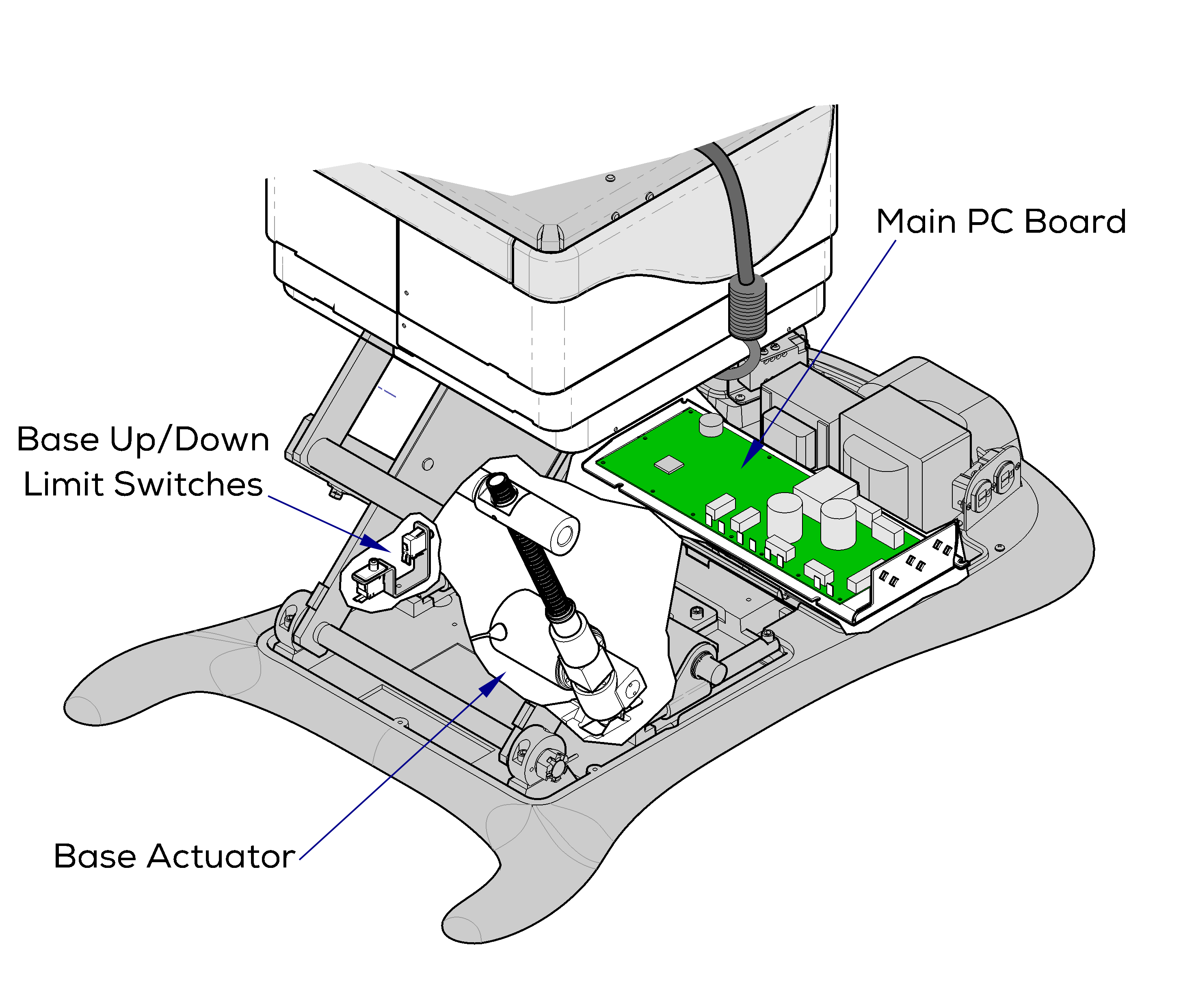
641 Chair Base Up/Down function Troubleshooting
This illustration shows only the components that affect the Base Up / Down function. Refer to:Base Up / Down for a detailed description of Base Up and Down operation.
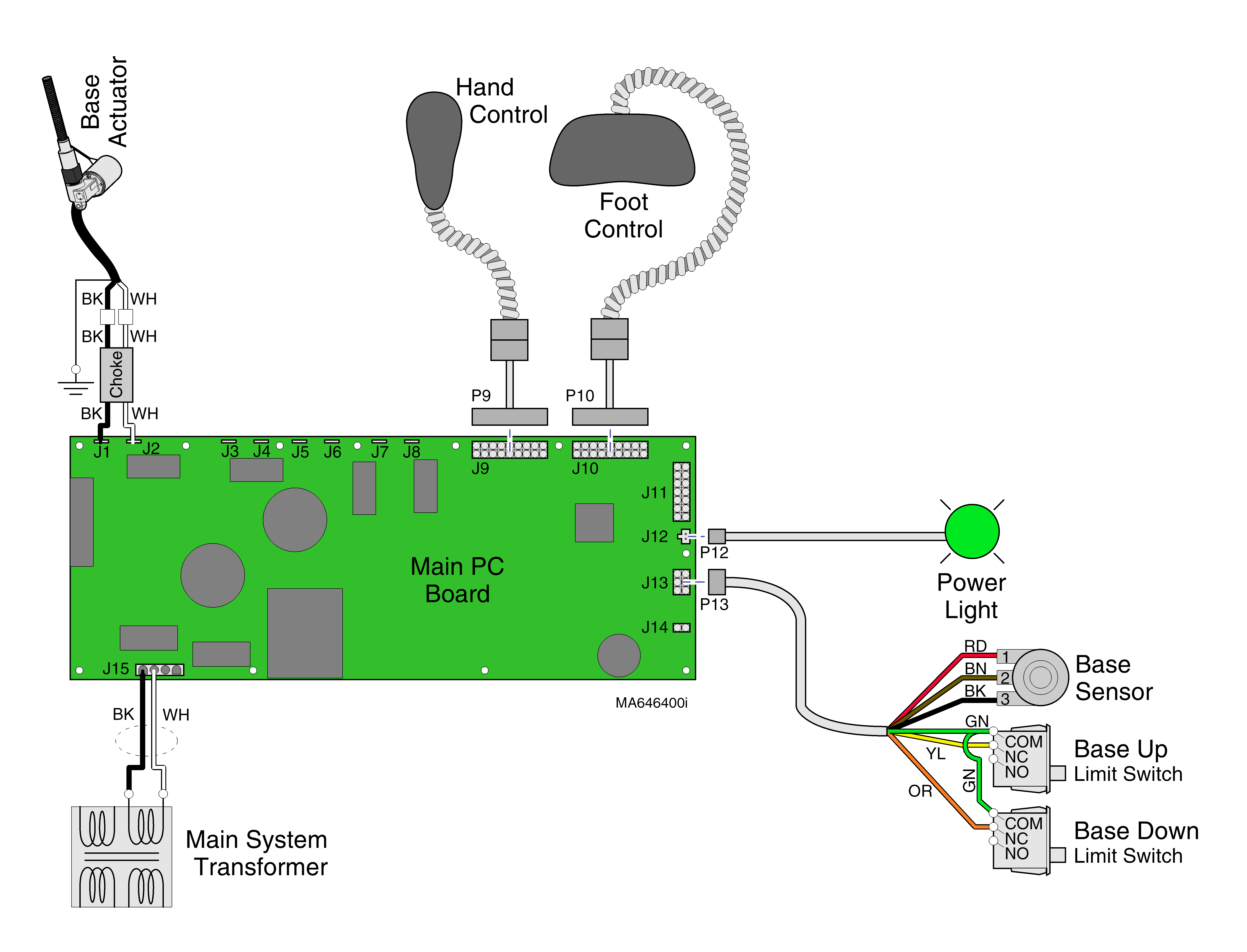
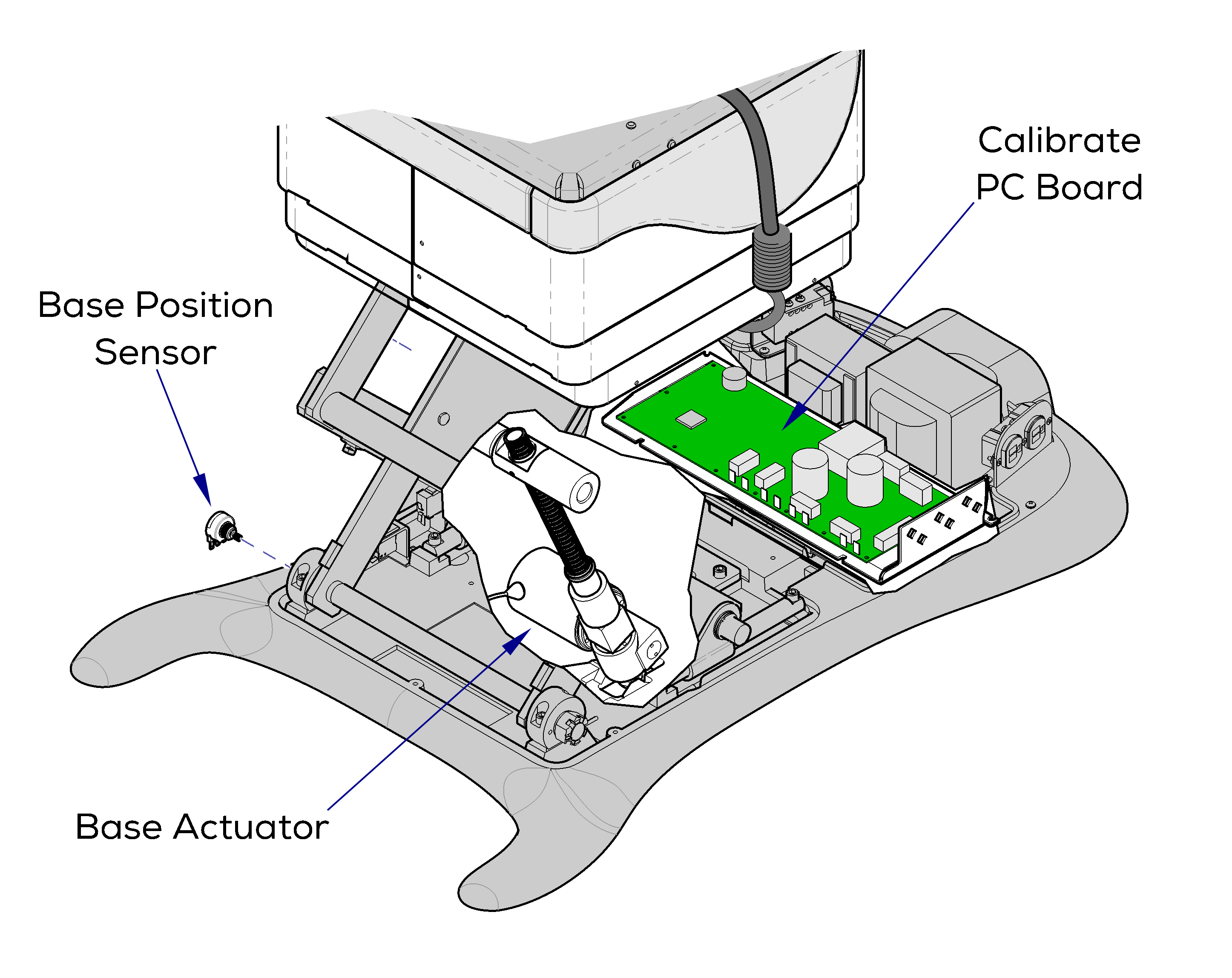
On models w/ rotational base, the Main System Transformer connections are supplied thru the Rotational Base PC Board - not shown.
•If Power Light is On, proper voltage is present at PC Board.
•If Power Light is off, Refer to: Power to the Table for troubleshooting.
•Black and white wires supply 48-54 VAC to power circuitry for the Base and Back actuators.
Refer to: Crash Avoidance System for a detailed description of crash position, and the table functions that are disabled.
Is There Power To The Table?
When voltage is present at the PC board, the power light is illuminated. Refer to: Power to the Table for description of current flow to the PC board.
Power To Foot / Hand Controls
Circuitry on the PC board supplies 8-10 VAC to the hand / foot control connection ports.
When the Base Up function is activated, current flows thru the hand / foot control, back to the PC board. Circuitry on the PC Board supplies approximately 48 VDC to the base actuator motor. The actuator motor runs and raises the table.
The PC board continuously monitors the Base Up limit switch and the Base position sensor. If the Base Up limit switch is tripped (open), the Base Up function will not operate. If the Base position sensor detects that the table has reached its upper limit, the Base Up function will not operate.
Actuator Motor runs until:
1.Hand / foot control button is released.
2.Base Up limit switch is tripped.
3.Emergency Stop button is pressed.
4.Position Sensor detects upper limit.
5.Overcurrent protection tripped.
6.Software time-out limit is reached, approximately 25 seconds.
When the Base Down function is activated, current flows thru the hand / foot control, back to the PC board. Circuitry on the PC Board supplies approximately 40 VDC to the base actuator motor. The actuator motor runs and lowers the table.
The PC board continuously monitors the Base Down limit switch and the Base position sensor. If the Base Down limit switch is tripped (open), the Base Down function will not operate. If the Base position sensor detects that the table is in a potential crash position, or that the base has reached its lower limit, the Base Down function will not operate*.
Actuator Motor runs until:
1.Hand / foot control button is released.
2.Base Down limit switch is tripped.
3.Emergency Stop button is pressed.
4.Crash Avoidance System activated*.
5.Position Sensor detects lower limit.
6.Overcurrent protection tripped.
7.Software time-out limit is reached, approximately 25 seconds.
1.Check for Loose / Damaged Wire Connections - Base Actuator, Base Up/Down Limit Switches, hand/foot control ports, black and white wires between main system transformer and PC board.
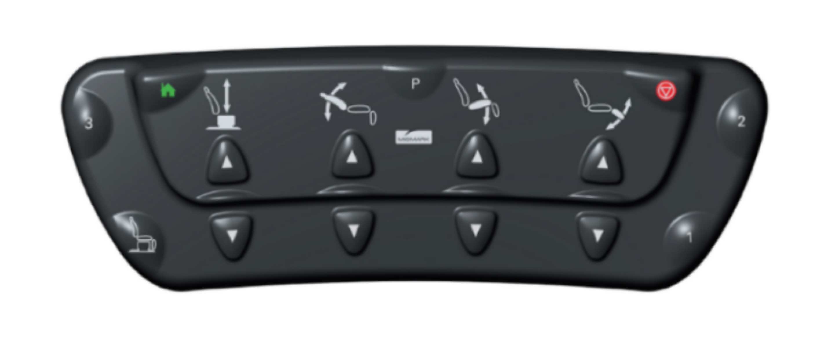
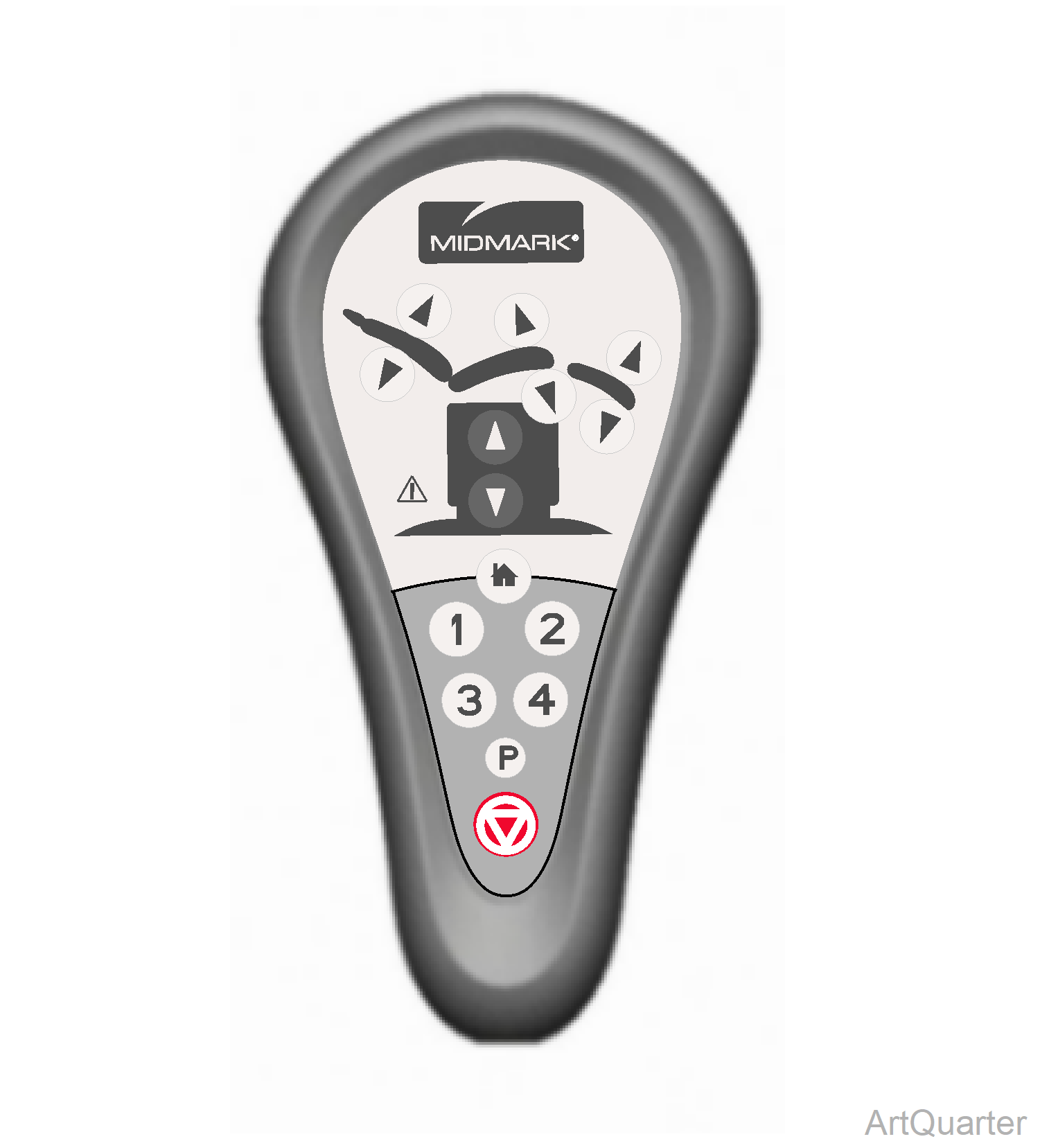
2.Hand / Foot Control Refer to: Hand and Foot Controls
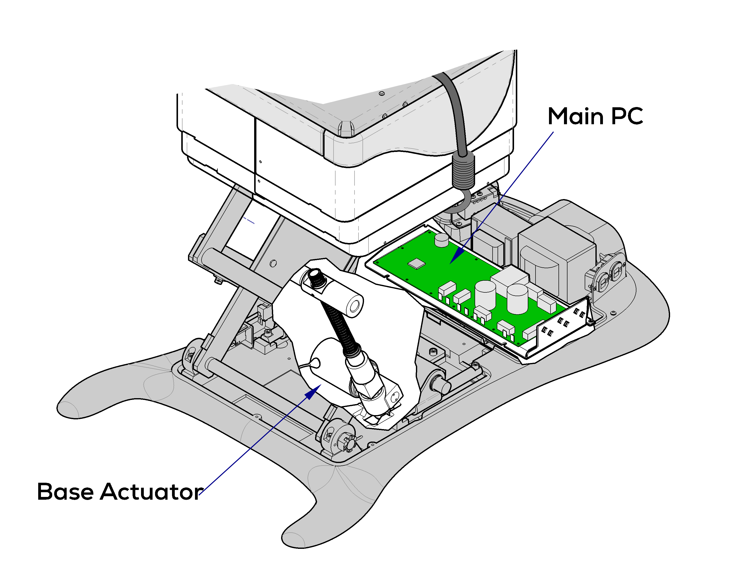
3.Base Actuator Refer to: Base Actuator / Limit Switches
4.Main PC Board Refer to: Main PC Board
If Base Down is inoperable, move the chair functions Back / Foot to full Up position and the Tilt to full Down position. If Base Down function becomes operable, Refer to: Crash Avoidance System
1.Check for Loose / Damaged Wire Connections - Hand/Foot Control and Base Up / Down Limit Switches
2.Base Up / Down Limit Switches Refer to:Base Actuator / Limit Switches
3.Hand / Foot Control Refer to:Hand and Foot Controls
4.Base Actuator Refer to:Base Actuator / Limit Switches
5.Main PC Board Refer to:Main PC Board
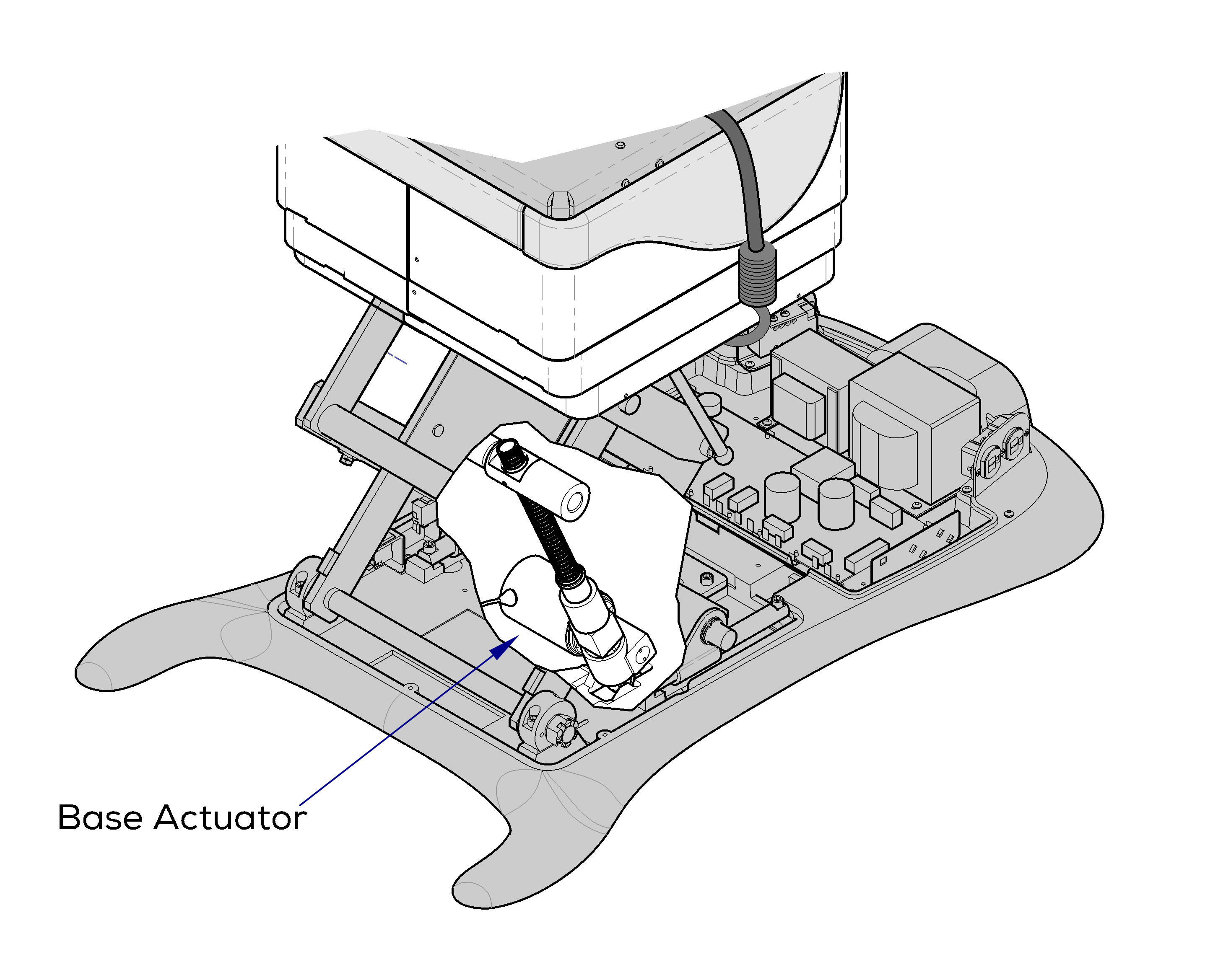
1.Base Actuator Refer to: Base Actuator / Limit Switches
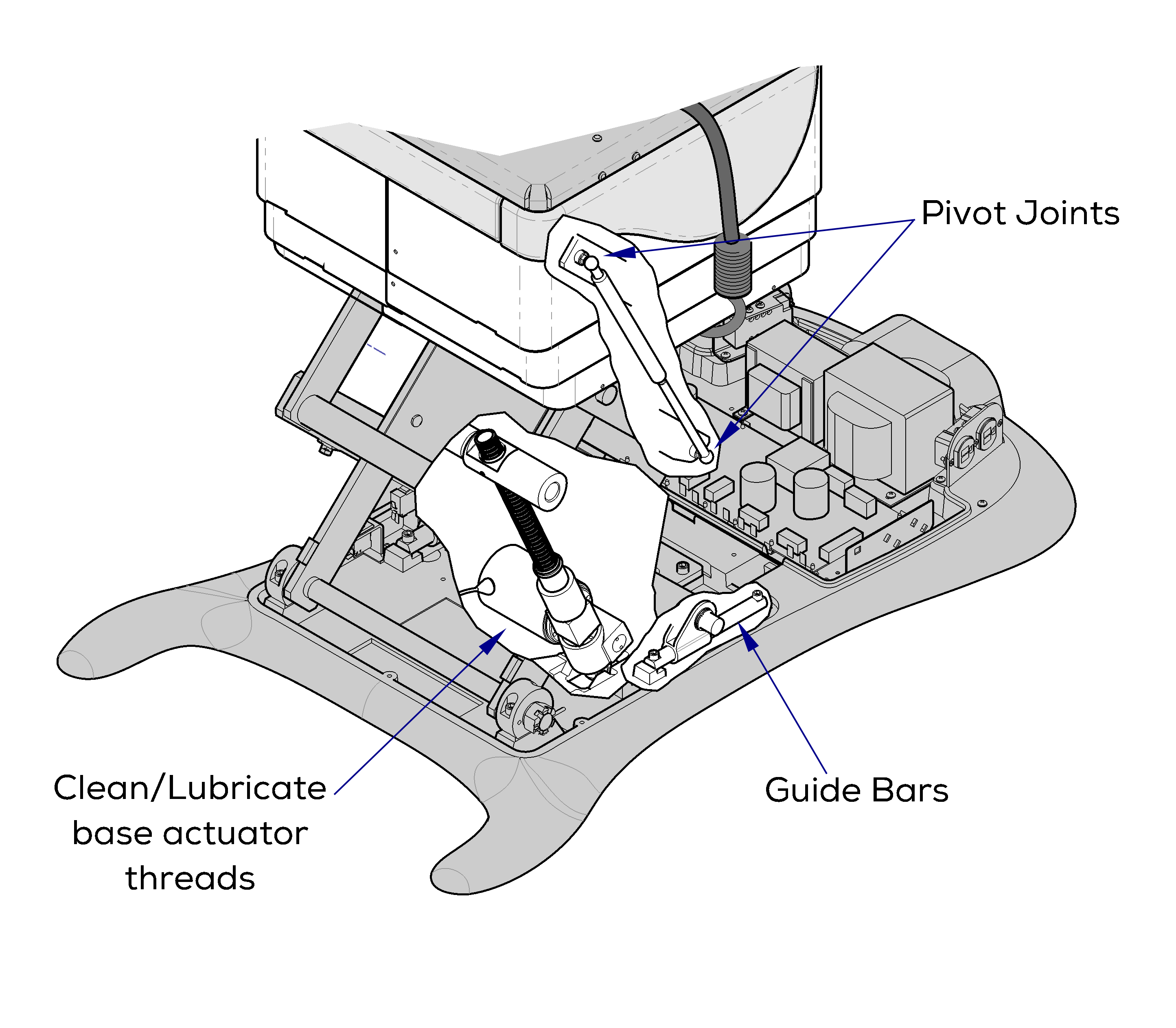
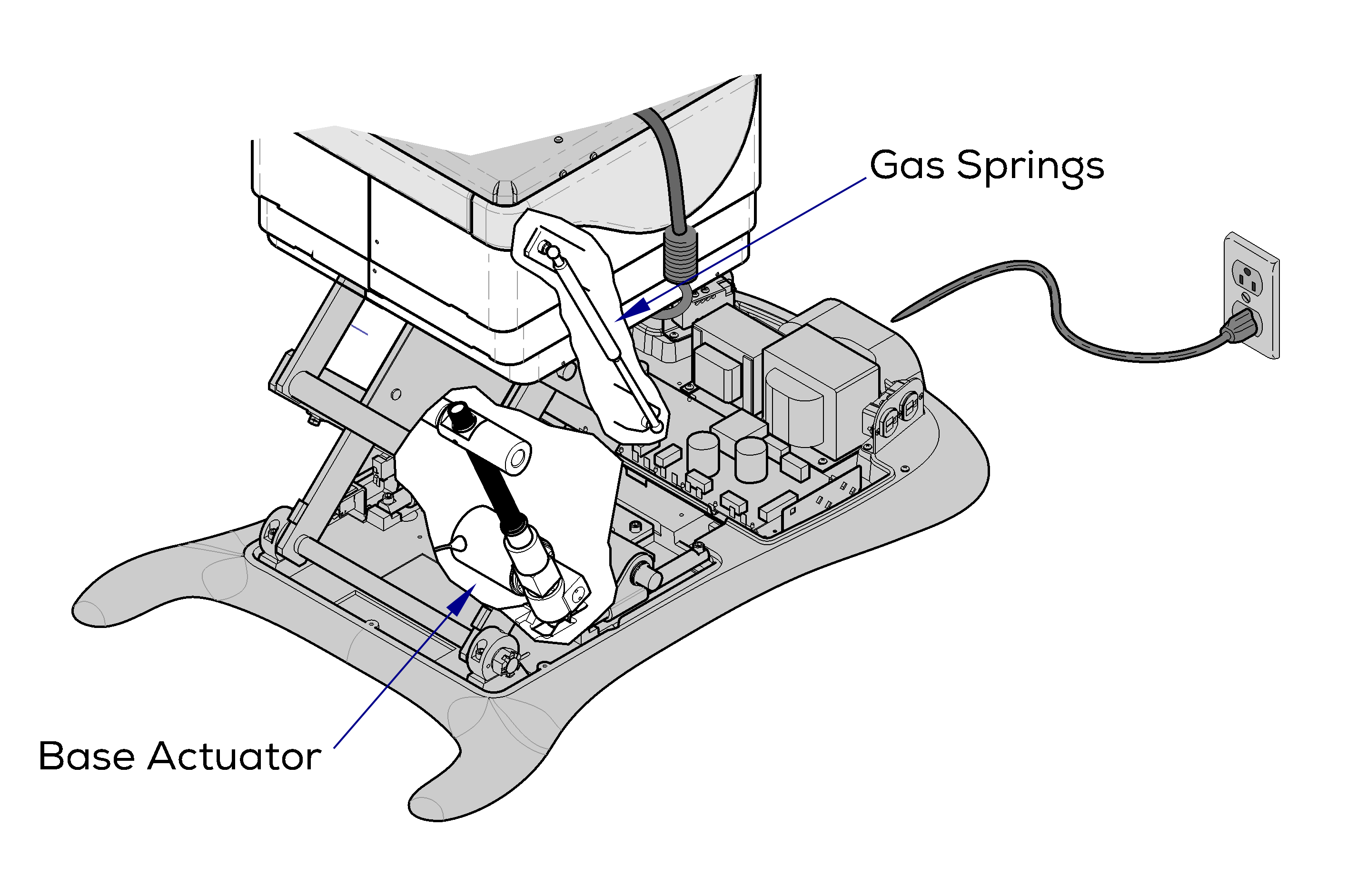
1.Clean / lubricate gas spring pivot joints Recommended lubricant: Lithium grease Refer to: Gas Springs
2.Clean / lubricate base actuator threads. Recommended lubricant: Lithium grease
3.Wipe guide bars with a clean, dry cloth. NEVER lubricate base slides / scissor mechanism.
4.Base Actuator Refer to:Base Actuator / Limit Switches
1.Did patient exceed 450 lb. weight limit? Inform staff that max. patient weight is 450 lbs. Refer to: General Information section
2.Low voltage to table.
| Required Voltage | |
|---|---|
| 115 VAC models | 115 +/_ 10% VAC |
| 230 VAC Models | 230 +/- 10% VAC |
3.Gas Springs Refer to: Gas Springs
4.Base Actuator Refer to: Base Actuator / Limit Switches
Before performing any of the checks on this page, move the chair functions Back / Foot to full up position and the Tilt to full down position. If Base Down function becomes operable, Refer to: Crash Avoidance System
1.Calibrate PC Board Refer to:Main PC Board
2.Check for loose / damaged wire connections - Base Position Sensor, Hand/Foot Controls
3.Base Position Sensor Refer to: Position Sensors
4.Base Actuator Refer to: Base Actuator / Limit Switches
