630 Chair Error Codes Troubleshooting
When S3 button is pressed, then released, you will hear a “beep” to indicate displaying of errors. Most recent displaying first. When switching errors, the board will again emit a “beep”. The displays will show “FFFF” if there are not ten errors to display. After all ten errors have been displayed you will hear three ”beeps”.
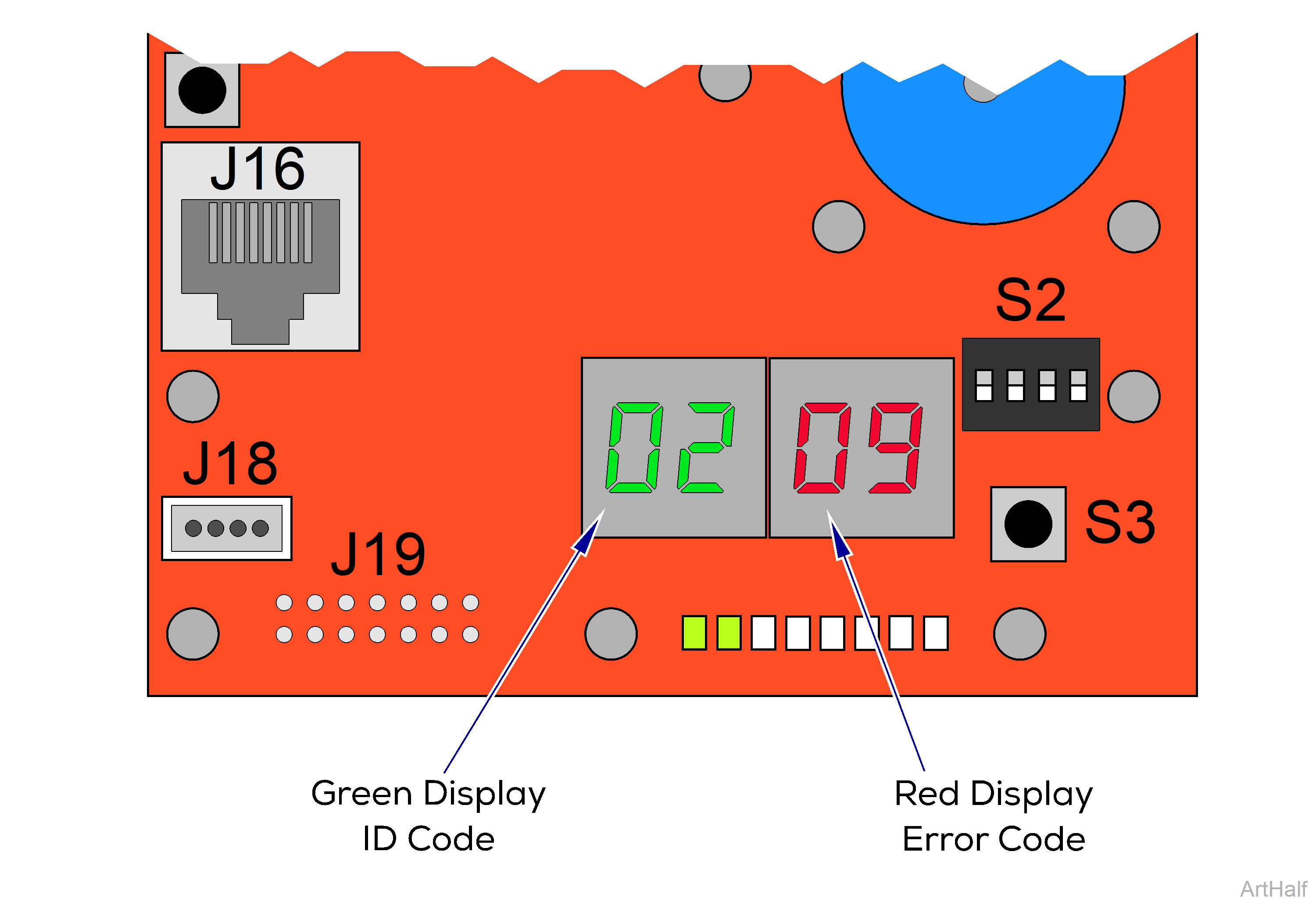
Green Display
The green display indicates the function or system where the problem occurs. Example: 02 = Base
Red Display
The red display indicates what problem or symptom was detected. Example: 09 = Switch Error
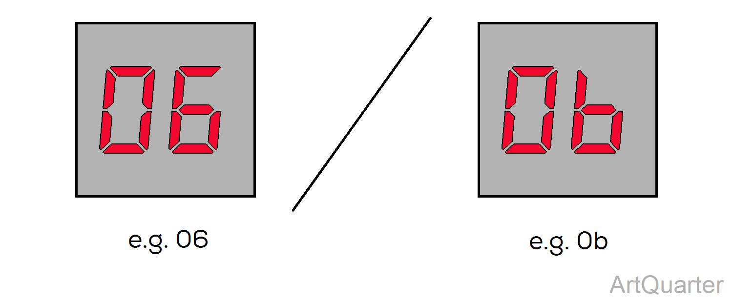
Use care when identifying Error Codes as some digits are similar.
1.Unplug chair power cord.
2.When the digital display darkens, move S2 switches three and four to ON (up).
3.Plug in chair power cord.
4.When the digital display darkens, press and release S3 button.
5. When all errors have been displayed, pressing and releasing S3 button again will repeat errors.
6.When recall is complete, unplug chair power cord.
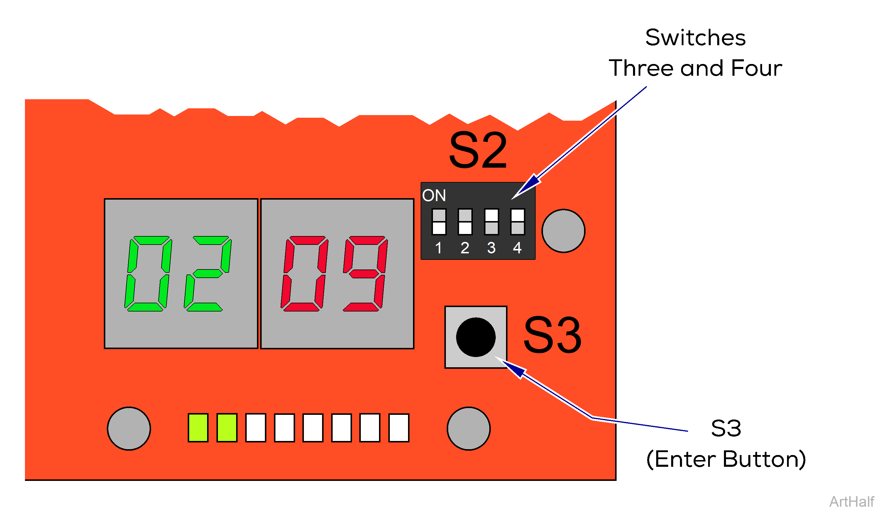
7.Move S2 switches three and four to OFF (down).
8.When the digital display darkens, plug in chair power cord.
|
Error Code |
Error Definition |
Probable Cause |
Correction |
|---|---|---|---|
|
00 |
Power-Up Image Fault |
Board Malfunction. |
Disconnect power cord for at least five seconds, then plug back in. |
|
Replace Machine Control PC Board. |
|||
|
01 |
Power-Up Memory Fault |
Board Malfunction. |
Disconnect power cord for at least five seconds, then plug back in. |
|
Replace Machine Control PC Board. |
|||
|
02 |
Power-Up Clock Fault |
Board Malfunction. |
Disconnect power cord for at least five seconds, then plug back in. |
|
Replace Machine Control PC Board. |
|||
|
03 |
Power-Up Clock Fault |
Board Malfunction. |
Disconnect power cord for at least five seconds, then plug back in. |
|
Replace Machine Control PC Board. |
|||
|
04 |
Power-Up Voltage Fault |
Loose connection. |
Check all connections between Machine Control Board and Power Supply PC Board. |
|
Board Malfunction. |
Disconnect power cord for at least five seconds, then plug back in. |
||
|
Replace Machine Control PC Board. |
|||
|
05 |
Process Execution Fault |
Board Malfunction. |
Disconnect power cord for at least five seconds, then plug back in. |
|
Replace Machine Control PC Board. |
|||
|
06 |
Power-Up Initialization Fault |
Board Malfunction. |
Disconnect power cord for at least five seconds, then plug back in. |
|
Replace Machine Control PC Board. |
|||
|
07 |
Headrest Clearance |
Position of chair. Refer to: Active Sensing Technology™ |
Activate Back Up, Base Up, and/or Tilt Down. |
|
08 |
Back Cover Clearance |
Position of chair. Refer to: Active Sensing Technology™ |
Activate Back Up, Base Up, and/or Tilt Down. |
|
09 |
Foot Clearance |
Position of chair. Refer to: Active Sensing Technology™ |
Activate Base Up, Tilt Up, and/or Foot Up. |
|
0A |
Programmability Time-out |
The Program button was pressed and no buttons were pressed within the allotted time. |
Error goes away by itself. |
|
0b |
Programmability Mistake |
The Program button was pressed to initiate programming a position and a non-programmable button was attempting to be programed. |
Error goes away by itself. |
|
0C |
Programmability Error |
The program command was received, and during the program time a proper command was received; however, at least one of the axis positions was out of range. |
Error goes away by itself. |
|
Run all functions to their maximum and minimum positions. |
|||
|
Calibrate Chair. Refer to: Calibration Procedure |
|||
|
0d |
Calibration Failed |
Chair not calibrated. |
Reference associated error code(s). Calibrate Chair. Refer to: Calibration Procedure |
|
0E |
Calibration Not Completed |
Chair not calibrated. Movement button on Hand / Foot Control pressed. |
Calibrate Chair. Refer to: Calibration Procedure |
|
0F |
Calibration Foot Extension Error |
Foot extension is extended. |
Move foot extension in. |
|
10 |
Low Voltage 5 VDC |
Loose connection. |
Check all connections between Machine Control Board and Power Supply PC Board. |
|
Board Malfunction. |
If LED (D-24) is illuminated, replace Machine Control PC Board. If LED (D-24) is not illuminated, replace Power Supply PC Board. |
||
|
11 |
Low Voltage 12 VDC |
Loose connection. |
Check all connections between Machine Control PC Board and Power Supply PC Board. |
|
Board Malfunction. |
If LED (D-25) is illuminated, replace Machine Control PC Board. If LED (D-25) is not illuminated, replace Power Supply PC Board. |
||
|
12 |
Low Voltage 48 VDC |
Loose connection. |
Check all connections between Machine Control PC Board and Power Supply PC Board. |
|
Board Malfunction. |
If LED’s (D-21 and D-22) are illuminated, replace Power Supply PC Board. If LED’s (D-21 and D-22) are not illuminated, test Power Toroid |
||
|
13 |
Temperature Out of Range |
Board Malfunction. |
Disconnect power cord for at least five seconds, then plug back in. |
|
Remove power for five minutes to allow Machine Control PC Board to cool, then reapply power. Check if Power Supply PC Board is overheating. |
|||
|
Replace Power Supply PC Board if overheating continues. |
|||
|
14 |
Control Lockout |
Control Lockout is activated. Refer to: Control Lockout |
Press and hold the Stop and Back Down buttons simultaneously for two seconds. You will hear a single “Beep” to indicate control lockout is disabled. |
|
15 |
Rotation Locked Out |
Rotation brake switch detected pressed during power-up. |
Disconnect power cord for at least five seconds, then plug back in. Ensure brake pedal is not depressed during power up. |
|
Loose wire connection. |
Check and secure wire connections at J12 on Machine Control PC Board and rotation brake switch. |
||
|
Rotation brake switch(es). |
Test / replace switch(es). |
||
|
16 |
Treatment Pan Out |
Treatment pan not in the stowed position. |
Push treatment pan all the way in. |
|
Loose wire connection. |
Check and secure wire connections at J6 on Machine Control PC Board and treatment pan switch. |
||
|
Treatment Pan switch. |
Test / replace switch. |
||
|
17 |
Communication Error to Motor Control |
Message failure. |
Error goes away by itself. |
|
Disconnect power cord for at least five seconds, then plug back in. |
|||
|
18 |
Communication Error to Motor Control |
Communication failure. |
Error goes away by itself. |
|
Disconnect power cord for at least five seconds, then plug back in. |
|||
|
19 |
Communication Error to Motor Control |
Communication failure. |
Error goes away by itself. |
|
Disconnect power cord for at least five seconds, then plug back in. |
|||
|
1A Flashing |
None |
Normal Operation. |
No action required. |
|
1A Continuously Illuminated |
Communication Error to Motor Control |
Loose wire connection. |
Check and secure wire connections at J3 on Power Supply PC Board and J13 on Motor Control Hub PC Board. |
|
Check and secure wire connections at J16 on Machine Control PC Board and J14 on Motor Control Hub PC Board. |
|||
|
Power Supply PC Board fuse(s) blown. |
Test / Replace F3 and F4 fuses on Power Supply PC Board. |
||
|
1b |
Communication Error to Motor Control |
Message failure. |
Error goes away by itself. |
|
Disconnect power cord for at least five seconds, then plug back in. |
|||
|
Loose wire connection. |
Check and secure wire connections at J3 on Power Supply PC Board and J13 on Motor Control Hub PC Board. |
||
|
Check and secure wire connections at J16 on Machine Control PC Board and J14 on Motor Control Hub PC Board. |
|||
|
Power Supply PC Board fuse(s) blown. |
Test / Replace F3 and F4 fuses on Power Supply PC Board. |
||
|
1C |
Communication Error to Motor Control |
Communication failure. |
Error goes away by itself. |
|
Disconnect power cord for at least five seconds, then plug back in. |
|||
|
1d |
Communication Error to Keypad |
Message failure. |
Error goes away by itself. |
|
Disconnect power cord for at least five seconds, then plug back in. |
|||
|
1E |
Communication Error to Keypad |
Communication failure. |
Error goes away by itself. |
|
Disconnect power cord for at least five seconds, then plug back in. |
|||
|
1F |
Communication Error to Keypad |
Communication failure. |
Error goes away by itself. |
|
Disconnect power cord for at least five seconds, then plug back in. |
|||
|
20 |
Communication Error to Keypad |
Message failure. |
Error goes away by itself. |
|
Disconnect power cord for at least five seconds, then plug back in. |
|||
|
21 |
Serial Diagnostics Port Error |
Communication failure. |
Error goes away by itself. |
|
Disconnect power cord for at least five seconds, then plug back in. |
|||
|
22 |
Corrupt Memory |
Last save to memory failed. |
Disconnect power cord for at least five seconds, then plug back in. |
|
Replace Machine Control PC Board. |
|||
|
23 |
Memory Save Error |
Saving to memory failed. |
Disconnect power cord for at least five seconds, then plug back in. |
|
Replace Machine Control PC Board. |
|||
|
24 |
Memory Recall Error |
Recalling information from memory failed. |
Disconnect power cord for at least five seconds, then plug back in. |
|
Replace Machine Control PC Board. |
|||
|
25 |
Memory Erase Error |
Erasing information from memory failed. |
Disconnect power cord for at least five seconds, then plug back in. |
|
Replace Machine Control PC Board. |
|||
|
26 |
Incorrect Movement |
An axis was detected moving when the commanded motion was to be stopped. |
Error goes away by itself. |
|
Disconnect power cord for at least five seconds, then plug back in. |
|
Error Code |
Error Definition |
Probable Cause |
Correction |
|---|---|---|---|
|
00 |
Power-Up Fault |
Board malfunction. |
Disconnect power cord for at least five seconds, then plug back in. |
|
Replace Power Supply PC Board. |
|||
|
01 |
Power-Up Initialization Fault |
Board malfunction. |
Disconnect power cord for at least five seconds, then plug back in. |
|
Replace Power Supply PC Board. |
|||
|
02 |
Calibration Failed / Not Complete |
The maximum position was unable to be set. |
Calibrate Chair. Refer to: Calibration Procedure |
|
A motor control error occurred. |
|||
|
03 |
Low Voltage 48 VDC |
Board Malfunction. |
Disconnect power cord for at least five seconds, then plug back in. |
|
If LED’s (D-21 and D-22) are illuminated, replace Power Supply PC Board. If LED’s (D-21 and D-22) are not illuminated, test Power Toroid |
|||
|
04 |
Low Voltage 48 VDC |
Board Malfunction. |
Disconnect power cord for at least five seconds, then plug back in. |
|
If LED’s (D-21 and D-22) are illuminated, replace Power Supply PC Board. If LED’s (D-21 and D-22) are not illuminated, test Power Toroid |
|||
|
05 |
Low Voltage 5 VDC |
Board Malfunction. |
Disconnect power cord for at least five seconds, then plug back in. |
|
Replace Power Supply PC Board. |
|||
|
06 |
Temperature Out of Range |
Board Malfunction. |
Disconnect power cord for at least five seconds, then plug back in. |
|
Remove power for five minutes to allow Power Supply PC Board to cool, then reapply power. |
|||
|
Replace Power Supply PC Board. |
|||
|
07 |
Active Sensing Technology™ activated. |
Active Sensing Technology™ activated. |
Remove object from under the foot section. |
|
Foot Smart Sensor Switches. |
Check and secure wire connections at J18 on Machine Control PC Board and at switches. Refer to: Fuses and Connections |
||
|
Check and secure Green and White wire connections at four pin inline connection next to Motor Control Hub PC Board. |
|||
|
Test / Replace switch(es). Refer to: Smart Sensor Switches |
|||
|
08 |
Position Out of Range |
Not calibrated. |
Calibrate Chair. Refer to: Calibration Procedure |
|
Limit Switch. |
Check and secure wire connections for Up limit switches. Refer to: Fuses and Connections |
||
|
Test / Replace switch(es). Refer to: Base Actuator / Limit Switches |
|||
|
09 |
Limit Switch |
Loose wire connection. |
Check and secure wire connections at J5 on Power Supply PC Board and at limit switch. Refer to: Fuses and Connections |
|
Base limit switch(es). |
Test / Replace switch(es). Refer to: Base Actuator / Limit Switches |
||
|
0A |
Overtravel Error |
Loose wire connection. |
Check and secure wire connections at J5 on Power Supply PC Board and at Overtravel limit switch. Refer to: Fuses and Connections Disconnect power cord for at least five seconds, then plug back in. |
|
Overtravel limit switch. |
Test / Replace switch. Refer to: Base Actuator / Limit Switches Disconnect power cord for at least five seconds, then plug back in. |
||
|
0b |
Hall Sensors |
Loose wire connection. |
Check and secure hall sensor wire connection at J7 on Power Supply PC Board. Refer to: Fuses and Connections |
|
Motor Failure. |
Replace Base actuator motor. |
||
|
0C |
Motor Current |
Excessive load on actuator. |
Check / Reduce patient load. (650 lb. Maximum) |
|
Check mechanical structure for binding. |
|||
|
0d |
Motor Run On Error |
The motor has been detected moving for a longer period of time than the run-on time allows. |
Check actuator / motor and limit switches. |
|
0E |
Motor Stall Error |
Excessive load on actuator. |
Check / Reduce patient load. (650 lb. Maximum) |
|
Check mechanical structure for binding. |
|||
|
Loose wire connection. |
Check and secure wire connections at J6 on Power Supply PC Board. Refer to: Fuses and Connections |
||
|
0F |
Motor Direction Error |
The motor is being commanded to move in one direction, but is actually moving in another. |
Check actuator / motor. |
|
10 |
Communication Error to Machine Control |
Message / Communication failure. |
Error goes away by itself. |
|
Disconnect power cord for at least five seconds, then plug back in. |
|||
|
11 |
Corrupt Memory |
Last save to memory failed. |
Disconnect power cord for at least five seconds, then plug back in. |
|
Replace Power Supply PC Board. |
|||
|
12 |
Memory Save Error |
Saving to memory failed. |
Disconnect power cord for at least five seconds, then plug back in. |
|
Replace Power Supply PC Board. |
|||
|
13 |
Memory Recall Error |
Recalling information from memory failed. |
Disconnect power cord for at least five seconds, then plug back in. |
|
Replace Power Supply PC Board. |
|||
|
14 |
Memory Erase Error |
Erasing information from memory failed. |
Disconnect power cord for at least five seconds, then plug back in. |
|
Replace Power Supply PC Board. |
|||
|
15 |
I2C Slave Not Present |
Power Supply PC Board fuse blown. |
Disconnect power cord for at least five seconds, then plug back in. |
|
Test / Replace F5 fuse on Power Supply PC Board. |
|||
|
16 |
I2C Slave Not Initialized |
Power Supply PC Board fuse blown. |
Disconnect power cord for at least five seconds, then plug back in. |
|
Test / Replace F5 fuse on Power Supply PC Board. |
|
Error Code |
Error Definition |
Probable Cause |
Correction |
|---|---|---|---|
|
00 |
Power-Up Fault |
Board malfunction. |
Disconnect power cord for at least five seconds, then plug back in. |
|
Replace Motor Control Hub PC Board. |
|||
|
01 |
Power-Up Initialization Fault |
Board malfunction. |
Disconnect power cord for at least five seconds, then plug back in. |
|
Replace Motor Control Hub PC Board. |
|||
|
02 |
Calibration Failed / Not Complete |
The maximum position was unable to be set. |
Calibrate Chair. Refer to: Calibration Procedure |
|
A motor control error occurred. |
|||
|
03 |
Low Voltage 48 VDC |
Loose connection. |
Check all connections between Power Supply PC Board and Motor Control Hub PC Board, and all connections between Machine Control PC Board and Motor Control Hub PC Board. |
|
Motor Control Hub PC Board fuse blown. |
Test / Replace F3 fuse on Motor Control Hub PC Board. |
||
|
Power Supply PC Board fuse(s) blown. |
Test / Replace F3 and F4 fuses on Power Supply PC Board. |
||
|
Board Malfunction. |
Disconnect power cord for at least five seconds, then plug back in. |
||
|
If LED’s (D-21 and D-22) are illuminated on Power Supply PC Board, check for 24 VDC at J-13 on Motor Control Hub Board. If voltage is present, replace Motor Control Hub PC Board. If LED’s (D-21 and D-22) are not illuminated, test Power Toroid |
|||
|
04 |
Low Voltage 48 VDC |
Loose connection. |
Check all connections between Power Supply PC Board and Motor Control Hub PC Board, and all connections between Machine Control PC Board and Motor Control Hub PC Board. |
|
Motor Control Hub PC Board fuse blown. |
Test / Replace F3 fuse on Motor Control Hub PC Board. |
||
|
Power Supply PC Board fuse(s) blown. |
Test / Replace F3 and F4 fuses on Power Supply PC Board. |
||
|
Board Malfunction. |
Disconnect power cord for at least five seconds, then plug back in. |
||
|
If LED’s (D-21 and D-22) are illuminated on Power Supply PC Board, check for 24 VDC at J-13 on Motor Control Hub Board. If voltage is present, replace Motor Control Hub PC Board. If LED’s (D-21 and D-22) are not illuminated, test Power Toroid |
|||
|
05 |
Low Voltage 5 VDC |
Loose connection. |
Check all connections between Power Supply PC Board and Motor Control Hub PC Board, and all connections between Machine Control PC Board and Motor Control Hub PC Board. |
|
Board Malfunction. |
Disconnect power cord for at least five seconds, then plug back in. |
||
|
Replace Motor Control Hub PC Board. |
|||
|
06 |
Temperature Out of Range |
Board Malfunction. |
Disconnect power cord for at least five seconds, then plug back in. |
|
Remove power for five minutes to allow Motor Control Hub PC Board to cool, then reapply power. |
|||
|
Replace Motor Control Hub PC Board. |
|||
|
08 |
Position Out of Range |
Not calibrated. |
Calibrate Chair. Refer to: Calibration Procedure |
|
Limit Switch. |
Check and secure wire connections for Up limit switches. Refer to: Fuses and Connections |
||
|
Test / Replace switch(es). Refer to: Back Actuator / Limit Switches |
|||
|
09 |
Limit Switch |
Loose wire connection. |
Check and secure wire connections at J12 on Motor Control Hub PC Board and at limit switch(es). Refer to: Fuses and Connections |
|
Back limit switch(es). |
Test / Replace switch(es). Refer to: Back Actuator / Limit Switches |
||
|
0A |
Overtravel Error |
Loose wire connection. |
Check and secure wire connections at J12 on Motor Control Hub PC Board and at Overtravel limit switch(es). Refer to: Fuses and Connections Disconnect power cord for at least five seconds, then plug back in. |
|
Overtravel limit switch(es). |
Test / Replace switch. Refer to: Back Actuator / Limit Switches Disconnect power cord for at least five seconds, then plug back in. |
||
|
0b |
Hall Sensors |
Loose wire connection. |
Check and secure hall sensor wire connection at J10 on Motor Control Hub PC Board. Refer to: Fuses and Connections |
|
Motor Failure. |
Replace Back actuator motor. |
||
|
0C |
Motor Current |
Excessive load on actuator. |
Check / Reduce patient load. (650 lb. Maximum) |
|
Check mechanical structure for binding. |
|||
|
0d |
Motor Run On Error |
The motor has been detected moving for a longer period of time than the run-on time allows. |
Check actuator / motor and limit switches. |
|
0E |
Motor Stall Error |
Excessive load on actuator. |
Check / Reduce patient load. (650 lb. Maximum) |
|
Check mechanical structure for binding. |
|||
|
Loose wire connection. |
Check and secure wire connections at J11 on Motor Control Hub PC Board. Refer to: Fuses and Connections |
||
|
0F |
Motor Direction Error |
The motor is being commanded to move in one direction, but is actually moving in another. |
Check actuator / motor. |
|
10 |
Communication Error to Machine Control |
Message / Communication failure. |
Error goes away by itself. |
|
Disconnect power cord for at least five seconds, then plug back in. |
|||
|
11 |
Corrupt Memory |
Last save to memory failed. |
Disconnect power cord for at least five seconds, then plug back in. |
|
Replace Motor Control Hub PC Board. |
|||
|
12 |
Memory Save Error |
Saving to memory failed. |
Disconnect power cord for at least five seconds, then plug back in. |
|
Replace Motor Control Hub PC Board. |
|||
|
13 |
Memory Recall Error |
Recalling information from memory failed. |
Disconnect power cord for at least five seconds, then plug back in. |
|
Replace Motor Control Hub PC Board. |
|||
|
14 |
Memory Erase Error |
Erasing information from memory failed. |
Disconnect power cord for at least five seconds, then plug back in. |
|
Replace Motor Control Hub PC Board. |
|||
|
15 |
I2C Slave Not Present |
Loose wire connection. |
Check and secure wire connections at J3 on Power Supply PC Board and J13 on Motor Control Hub PC Board. Refer to: Fuses and Connections |
|
Check and secure wire connections at J16 on Machine Control PC Board and J14 on Motor Control Hub PC Board. Refer to: Fuses and Connections |
|||
|
Power Supply PC Board fuse(s) blown. |
Test / Replace F3 and F4 fuses on Power Supply PC Board. |
||
|
Motor Control Hub PC Board. |
Check supply power to Motor Control Hub PC Board. Refer to: Motor Control Hub PC Board Supply Power |
||
|
Power Supply PC Board. |
Check supply power to Motor Control Hub PC Board. Refer to: Motor Control Hub PC Board Supply Power |
||
|
16 |
I2C Slave Not Initialized |
Loose wire connection. |
Check and secure wire connections at J3 on Power Supply PC Board and J13 on Motor Control Hub PC Board. Refer to: Fuses and Connections |
|
Check and secure wire connections at J16 on Machine Control PC Board and J14 on Motor Control Hub PC Board. Refer to: Fuses and Connections |
|||
|
Power Supply PC Board fuse(s) blown. |
Test / Replace F3 and F4 fuses on Power Supply PC Board. |
||
|
Motor Control Hub PC Board. |
Check supply power to Motor Control Hub PC Board. Refer to: Motor Control Hub PC Board Supply Power |
||
|
Power Supply PC Board. |
Check supply power to Motor Control Hub PC Board. Refer to: Motor Control Hub PC Board Supply Power |
|
Error Code |
Error Definition |
Probable Cause |
Correction |
|---|---|---|---|
|
00 |
Power-Up Fault |
Board malfunction. |
Disconnect power cord for at least five seconds, then plug back in. |
|
Replace Motor Control Hub PC Board. |
|||
|
01 |
Power-Up Initialization Fault |
Board malfunction. |
Disconnect power cord for at least five seconds, then plug back in. |
|
Replace Motor Control Hub PC Board. |
|||
|
02 |
Calibration Failed / Not Complete |
The maximum position was unable to be set. |
Calibrate Chair. Refer to: Calibration Procedure |
|
A motor control error occurred. |
|||
|
03 |
Low Voltage 48 VDC |
Loose connection. |
Check all connections between Power Supply PC Board and Motor Control Hub PC Board, and all connections between Machine Control PC Board and Motor Control Hub PC Board. |
|
Motor Control Hub PC Board fuse blown. |
Test / Replace F2 fuse on Motor Control Hub PC Board. |
||
|
Power Supply PC Board fuse(s) blown. |
Test / Replace F3 and F4 fuses on Power Supply PC Board. |
||
|
Board Malfunction. |
Disconnect power cord for at least five seconds, then plug back in. |
||
|
If LED’s (D-21 and D-22) are illuminated on Power Supply PC Board, check for 24 VDC at J-13 on Motor Control Hub Board. If voltage is present, replace Motor Control Hub PC Board. If LED’s (D-21 and D-22) are not illuminated, test Power Toroid |
|||
|
04 |
Low Voltage 48 VDC |
Loose connection. |
Check all connections between Power Supply PC Board and Motor Control Hub PC Board, and all connections between Machine Control PC Board and Motor Control Hub PC Board. |
|
Motor Control Hub PC Board fuse blown. |
Test / Replace F2 fuse on Motor Control Hub PC Board. |
||
|
Power Supply PC Board fuse(s) blown. |
Test / Replace F3 and F4 fuses on Power Supply PC Board. |
||
|
Board Malfunction. |
Disconnect power cord for at least five seconds, then plug back in. |
||
|
If LED’s (D-21 and D-22) are illuminated on Power Supply PC Board, check for 24 VDC at J-13 on Motor Control Hub Board. If voltage is present, replace Motor Control Hub PC Board. If LED’s (D-21 and D-22) are not illuminated, test Power Toroid |
|||
|
05 |
Low Voltage 5 VDC |
Loose connection. |
Check all connections between Power Supply PC Board and Motor Control Hub PC Board, and all connections between Machine Control PC Board and Motor Control Hub PC Board. |
|
Board Malfunction. |
Disconnect power cord for at least five seconds, then plug back in. |
||
|
Replace Motor Control Hub PC Board. |
|||
|
06 |
Temperature Out of Range |
Board Malfunction. |
Disconnect power cord for at least five seconds, then plug back in. |
|
Remove power for five minutes to allow Motor Control Hub PC Board to cool, then reapply power. |
|||
|
Replace Motor Control Hub PC Board. |
|||
|
07 |
Active Sensing Technology™ activated. |
Active Sensing Technology™ activated. |
Remove object from under the foot section and/or from the top of the column. |
|
Foot Smart Sensor Switches. |
Check and secure wire connections at J18 on Machine Control PC Board and at switches. Refer to: Fuses and Connections |
||
|
Check and secure Green and White wire connections at four pin inline connection next to Motor Control Hub PC Board. |
|||
|
Test / Replace switch(es). Refer to: Smart Sensor Switches |
|||
|
Seat Smart Sensor Switches. |
Check and secure wire connections at J18 on Machine Control PC Board and at switches. Refer to: Fuses and Connections |
||
|
Check and secure wire connections at two pin inline connection next to Motor Control Hub PC Board. |
|||
|
Test / Replace switch(es). Refer to: Smart Sensor Switches |
|||
|
08 |
Position Out of Range |
Not calibrated. |
Calibrate Chair. Refer to: Calibration Procedure |
|
Limit Switch. |
Check and secure wire connections for Up limit switches. Refer to: Fuses and Connections |
||
|
Test / Replace switch(es). Refer to: Tilt Actuator / Limit Switches |
|||
|
09 |
Limit Switch |
Loose wire connection. |
Check and secure wire connections at J8 on Motor Control Hub PC Board and at limit switch(es). Refer to: Fuses and Connections |
|
Tilt limit switch(es). |
Test / Replace switch(es). Refer to: Tilt Actuator / Limit Switches |
||
|
0A |
Overtravel Error |
Loose wire connection. |
Check and secure wire connections at J8 on Motor Control Hub PC Board and at Overtravel limit switch(es). Refer to: Fuses and Connections Disconnect power cord for at least five seconds, then plug back in. |
|
Tilt Up Overtravel limit switch. |
Test / Replace switch. Refer to: Tilt Actuator / Limit Switches Disconnect power cord for at least five seconds, then plug back in. |
||
|
0b |
Hall Sensors |
Loose wire connection. |
Check and secure hall sensor wire connection at J6 on Motor Control Hub PC Board. Refer to: Fuses and Connections |
|
Motor Failure. |
Replace Tilt actuator motor. |
||
|
0C |
Motor Current |
Excessive load on actuator. |
Check / Reduce patient load. (650 lb. Maximum) |
|
Check mechanical structure for binding. |
|||
|
0d |
Motor Run On Error |
The motor has been detected moving for a longer period of time than the run-on time allows. |
Check actuator / motor and limit switches. |
|
0E |
Motor Stall Error |
Excessive load on actuator. |
Check / Reduce patient load. (650 lb. Maximum) |
|
Check mechanical structure for binding. |
|||
|
Loose wire connection. |
Check and secure wire connections at J7 on Motor Control Hub PC Board. Refer to: Fuses and Connections |
||
|
0F |
Motor Direction Error |
The motor is being commanded to move in one direction, but is actually moving in another. |
Check actuator / motor. |
|
10 |
Communication Error to Machine Control |
Message / Communication failure. |
Error goes away by itself. |
|
Disconnect power cord for at least five seconds, then plug back in. |
|||
|
11 |
Corrupt Memory |
Last save to memory failed. |
Disconnect power cord for at least five seconds, then plug back in. |
|
Replace Motor Control Hub PC Board. |
|||
|
12 |
Memory Save Error |
Saving to memory failed. |
Disconnect power cord for at least five seconds, then plug back in. |
|
Replace Motor Control Hub PC Board. |
|||
|
13 |
Memory Recall Error |
Recalling information from memory failed. |
Disconnect power cord for at least five seconds, then plug back in. |
|
Replace Motor Control Hub PC Board. |
|||
|
14 |
Memory Erase Error |
Erasing information from memory failed. |
Disconnect power cord for at least five seconds, then plug back in. |
|
Replace Motor Control Hub PC Board. |
|||
|
15 |
I2C Slave Not Present |
Loose wire connection. |
Check and secure wire connections at J3 on Power Supply PC Board and J13 on Motor Control Hub PC Board. Refer to: Fuses and Connections |
|
Check and secure wire connections at J16 on Machine Control PC Board and J14 on Motor Control Hub PC Board. Refer to: Fuses and Connections |
|||
|
Power Supply PC Board fuse(s) blown. |
Test / Replace F3 and F4 fuses on Power Supply PC Board. |
||
|
Motor Control Hub PC Board. |
Check supply power to Motor Control Hub PC Board. Refer to: Motor Control Hub PC Board Supply Power |
||
|
Power Supply PC Board. |
Check supply power to Motor Control Hub PC Board. Refer to: Motor Control Hub PC Board Supply Power |
||
|
16 |
I2C Slave Not Initialized |
Loose wire connection. |
Check and secure wire connections at J3 on Power Supply PC Board and J13 on Motor Control Hub PC Board. Refer to: Fuses and Connections |
|
Check and secure wire connections at J16 on Machine Control PC Board and J14 on Motor Control Hub PC Board. Refer to: Fuses and Connections |
|||
|
Power Supply PC Board fuse(s) blown. |
Test / Replace F3 and F4 fuses on Power Supply PC Board. |
||
|
Motor Control Hub PC Board. |
Check supply power to Motor Control Hub PC Board. Refer to: Motor Control Hub PC Board Supply Power |
||
|
Power Supply PC Board. |
Check supply power to Motor Control Hub PC Board. Refer to: Motor Control Hub PC Board Supply Power |
|
Error Code |
Error Definition |
Probable Cause |
Correction |
|---|---|---|---|
|
00 |
Power-Up Fault |
Board malfunction. |
Disconnect power cord for at least five seconds, then plug back in. |
|
Replace Motor Control Hub PC Board. |
|||
|
01 |
Power-Up Initialization Fault |
Board malfunction. |
Disconnect power cord for at least five seconds, then plug back in. |
|
Replace Motor Control Hub PC Board. |
|||
|
02 |
Calibration Failed / Not Complete |
The maximum position was unable to be set. |
Calibrate Chair. Refer to: Calibration Procedure |
|
A motor control error occurred. |
|||
|
03 |
Low Voltage 48 VDC |
Loose connection. |
Check all connections between Power Supply PC Board and Motor Control Hub PC Board, and all connections between Machine Control PC Board and Motor Control Hub PC Board. |
|
Motor Control Hub PC Board fuse blown. |
Test / Replace F1 fuse on Motor Control Hub PC Board. |
||
|
Power Supply PC Board fuse(s) blown. |
Test / Replace F3 and F4 fuses on Power Supply PC Board. |
||
|
Board Malfunction. |
Disconnect power cord for at least five seconds, then plug back in. |
||
|
If LED’s (D-21 and D-22) are illuminated on Power Supply PC Board, check for 24 VDC at J-13 on Motor Control Hub Board. If voltage is present, replace Motor Control Hub PC Board. If LED’s (D-21 and D-22) are not illuminated, test Power Toroid |
|||
|
04 |
Low Voltage 48 VDC |
Loose connection. |
Check all connections between Power Supply PC Board and Motor Control Hub PC Board, and all connections between Machine Control PC Board and Motor Control Hub PC Board. |
|
Motor Control Hub PC Board fuse blown. |
Test / Replace F1 fuse on Motor Control Hub PC Board. |
||
|
Power Supply PC Board fuse(s) blown. |
Test / Replace F3 and F4 fuses on Power Supply PC Board. |
||
|
Board Malfunction. |
Disconnect power cord for at least five seconds, then plug back in. |
||
|
If LED’s (D-21 and D-22) are illuminated on Power Supply PC Board, check for 24 VDC at J-13 on Motor Control Hub Board. If voltage is present, replace Motor Control Hub PC Board. If LED’s (D-21 and D-22) are not illuminated, test Power Toroid |
|||
|
05 |
Low Voltage 5 VDC |
Loose connection. |
Check all connections between Power Supply PC Board and Motor Control Hub PC Board, and all connections between Machine Control PC Board and Motor Control Hub PC Board. |
|
Board Malfunction. |
Disconnect power cord for at least five seconds, then plug back in. |
||
|
Replace Motor Control Hub PC Board. |
|||
|
06 |
Temperature Out of Range |
Board Malfunction. |
Disconnect power cord for at least five seconds, then plug back in. |
|
Remove power for five minutes to allow Motor Control Hub PC Board to cool, then reapply power. |
|||
|
Replace Motor Control Hub PC Board. |
|||
|
07 |
Active Sensing Technology™ activated. |
Active Sensing Technology™ activated. |
Remove object from under the foot section. |
|
Foot Smart Sensor Switches. |
Check and secure wire connections at J18 on Machine Control PC Board and at switches. Refer to: Fuses and Connections |
||
|
Check and secure Green and White wire connections at four pin inline connection next to Motor Control Hub PC Board. |
|||
|
Test / Replace switch(es). Refer to: Smart Sensor Switches |
|||
|
08 |
Position Out of Range |
Not calibrated. |
Calibrate Chair. Refer to: Calibration Procedure |
|
Limit Switch. |
Check and secure wire connections for Up limit switches. Refer to: Fuses and Connections |
||
|
Test / Replace switch(es). Refer to: Foot Actuator / Limit Switches |
|||
|
09 |
Limit Switch |
Loose wire connection. |
Check and secure wire connections at J4 on Motor Control Hub PC Board and at limit switch(es). Refer to: Fuses and Connections |
|
Foot limit switch(es). |
Test / Replace switch(es). Refer to: Foot Actuator / Limit Switches |
||
|
0A |
Overtravel Error |
Loose wire connection. |
Check and secure wire connections at J4 on Motor Control Hub PC Board and at Overtravel limit switch(es). Refer to: Fuses and Connections Disconnect power cord for at least five seconds, then plug back in. |
|
Overtravel limit switch(es). |
Test / Replace switch. Refer to: Foot Actuator / Limit Switches Disconnect power cord for at least five seconds, then plug back in. |
||
|
0b |
Hall Sensors |
Loose wire connection. |
Check and secure hall sensor wire connection at J2 on Motor Control Hub PC Board. Refer to: Fuses and Connections |
|
Motor Failure. |
Replace Foot actuator motor. |
||
|
0C |
Motor Current |
Excessive load on actuator. |
Check / Reduce patient load. (650 lb. Maximum) |
|
Check mechanical structure for binding. |
|||
|
0d |
Motor Run On Error |
The motor has been detected moving for a longer period of time than the run-on time allows. |
Check actuator / motor and limit switches. |
|
0E |
Motor Stall Error |
Excessive load on actuator. |
Check / Reduce patient load. (650 lb. Maximum) |
|
Check mechanical structure for binding. |
|||
|
Loose wire connection. |
Check and secure wire connections at J3 on Motor Control Hub PC Board. Refer to: Fuses and Connections |
||
|
0F |
Motor Direction Error |
The motor is being commanded to move in one direction, but is actually moving in another. |
Check actuator / motor. |
|
10 |
Communication Error to Machine Control |
Message / Communication failure. |
Error goes away by itself. |
|
Disconnect power cord for at least five seconds, then plug back in. |
|||
|
11 |
Corrupt Memory |
Last save to memory failed. |
Disconnect power cord for at least five seconds, then plug back in. |
|
Replace Motor Control Hub PC Board. |
|||
|
12 |
Memory Save Error |
Saving to memory failed. |
Disconnect power cord for at least five seconds, then plug back in. |
|
Replace Motor Control Hub PC Board. |
|||
|
13 |
Memory Recall Error |
Recalling information from memory failed. |
Disconnect power cord for at least five seconds, then plug back in. |
|
Replace Motor Control Hub PC Board. |
|||
|
14 |
Memory Erase Error |
Erasing information from memory failed. |
Disconnect power cord for at least five seconds, then plug back in. |
|
Replace Motor Control Hub PC Board. |
|||
|
15 |
I2C Slave Not Present |
Loose wire connection. |
Check and secure wire connections at J3 on Power Supply PC Board and J13 on Motor Control Hub PC Board. Refer to: Fuses and Connections |
|
Check and secure wire connections at J16 on Machine Control PC Board and J14 on Motor Control Hub PC Board. Refer to: Fuses and Connections |
|||
|
Power Supply PC Board fuse(s) blown. |
Test / Replace F3 and F4 fuses on Power Supply PC Board. |
||
|
Motor Control Hub PC Board. |
Check supply power to Motor Control Hub PC Board. Refer to: Motor Control Hub PC Board Supply Power |
||
|
Power Supply PC Board. |
Check supply power to Motor Control Hub PC Board. Refer to: Motor Control Hub PC Board Supply Power |
||
|
16 |
I2C Slave Not Initialized |
Loose wire connection. |
Check and secure wire connections at J3 on Power Supply PC Board and J13 on Motor Control Hub PC Board. Refer to: Fuses and Connections |
|
Check and secure wire connections at J16 on Machine Control PC Board and J14 on Motor Control Hub PC Board. Refer to: Fuses and Connections |
|||
|
Power Supply PC Board fuse(s) blown. |
Test / Replace F3 and F4 fuses on Power Supply PC Board. |
||
|
Motor Control Hub PC Board. |
Check supply power to Motor Control Hub PC Board. Refer to: Motor Control Hub PC Board Supply Power |
||
|
Power Supply PC Board. |
Check supply power to Motor Control Hub PC Board. Refer to: Motor Control Hub PC Board Supply Power |
